6. Die-to-die SAD reverse: The same as above, but in the reverse direction.
7. Supplemental optimizer to black alignment patterns, forward: These are extra patterns to help with
optimizer to black alignment visibility. They can be used to evaluate alignment in both the SAD and PAD
directions. The magnitude of misalignment should be the same as that observed in the other forward
diagnostics, but the thicker lines may be easier to see. This group of patterns is printed in the forward
direction.
8. Supplemental optimizer to black alignment patterns, reverse: The same as above, but in the reverse
direction.
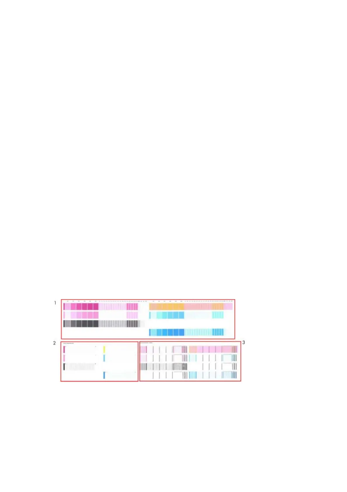
9. Error legend: This is a reference scale to help determine the magnitude of alignment errors.
10. Die overlap: Misalignment between the lines will be a combination of SAD and PAD errors. If the die-to-
die SAD forward is well aligned then the error in this pattern can be attributed to PAD.
Corrective action
In order to solve any problem in the alignment, perform the following:
●
Repeat the printhead alignment. Most recommended substrates are glossy papers where printhead
alignment accuracy is best. There are some substrate types that are not suitable for printhead
alignment (transparent, translucent)
●
Try cleaning the printheads if the error continues.
●
If the error persists, replace the affected printhead.
●
If there is an issue in the ThetaZ and it cannot be fixed, check if the substrate is working with the OMAS
sensor, and that the substrate is not loaded with excessive skew. There are some substrates that
cannot be controlled by the OMAS sensor. If the substrate is a type that should work with the OMAS
sensor, check the functionality of the sensor.
Plot for escalation only
To print this test plot, go to Menu List > 2. Image Quality Plots > 2.4 Health > 2.4.3 Only For Escalations.
There are two identical plots to this test and each plot has three parts to it. The first plot refers to the rear
printheads (number 1, 3, 5), while the second plot refers to the front printheads (2, 4, 6).
This plot is only printed at the request of the HP Division, or in case further help is required and there is need
to escalate an image quality issue to HP Division.
Geometry check
The Geometry check print test is a simple template designed to check the printer’s length accuracy and figure
distortion performance. To print this test plot go to Menu List > 2. Image Quality Plots > 2.5 Geometry Check.
196 Chapter 5 Print quality ENWW
 Loading...


