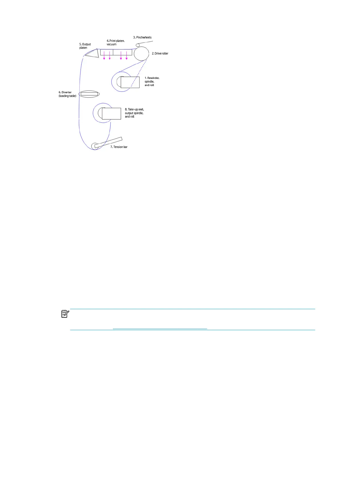
1. The substrate is loaded onto the input spindle (1), which is driven by the rewinder mechanism to
provide back tension to the substrate. The substrate is fed through the input platen where an optical
sensor detects substrate presence, around the drive roller (2), under the pinchwheels (3), over the
print zone (4) and the overdrive platen (5), and finally it is either left free or looped through the
diverter (6) through the tension bar (7) to be collected on the take-up reel (8).
2. The rewinder has a motor that primarily acts as a brake to maintain tension on the substrate. The
rewinder may turn in either direction, depending on which is the printable side of the input substrate roll
and its winding direction.
3. The drive roller also has a motor, and is the primary component that advances the substrate. The
substrate is pressed to the drive roller by the pinchwheels, ensuring a smooth substrate advance. The
motor receives feedback from an encoder located at the left side of the roller, inside a protected
enclosure on the left of the left sideplate.
4. The surface of the substrate path where the substrate is printed is called the print platen. The print
platen is designed to give minimal resistance to the substrate advance, and includes suction holes that
apply vacuum to the substrate.
5. The printer detects and controls the substrate advance. The OMAS sensor, located on a special cut-out
section of the print platen, is a sensor that is able to detect very small errors in the advance of the
substrate. These errors are communicated to the motors on the drive roller, and small correctional
adjustments are applied to the movement of the substrate.
NOTE: The OMAS sensor cannot see the fibers on some substrates, such as transparent substrate or
very dark or very reflective substrates. In these cases, the OMAS sensor can be disabled. To disable the
OMAS sensor, see
1.3.3 Enable/Disable OMAS on page 167.
6. The vacuum pressure is adjusted depending on the substrate type and print options used. It draws the
substrate to the print platen, making sure that the substrate is flat.
7. After the platen, the substrate goes through the curing zone and finally leaves the printer, either to be
collected on the take-up reel or to be cut.
8. When the take-up reel is in use, the substrate must be threaded, first passing in front of the loading
table used as a diverter, then under the tension bar and rerouted to the output roll loaded in the take-
up reel. This system creates tension on the outgoing substrate for proper winding. The take-up reel can
operate in both directions with the rewinder, winding with the printed face outside or inside.
Startup, substrate load, substrate selection
During startup, the printer checks that the substrate path components are functioning correctly. When
shutting down, if a substrate is loaded, the printer remembers the substrate definition. This may be modified
through the front panel with the option ’Change loaded substrate’ from the substrate menu list.
ENWW Substrate path 23
 Loading...


