Rockwell Automation Publication 2198-UM004D-EN-P - December 2022 497
Appendix C Use Add-On Instructions
Opr Add-On Instruction
Configuration
Use the video on the PCDC to create and install the Device Object and Motion
Instruction Add-On Instructions. Once the Operation Add-On Instructions are
created, use the sample logic that is created as guidance for creating your
application logic.
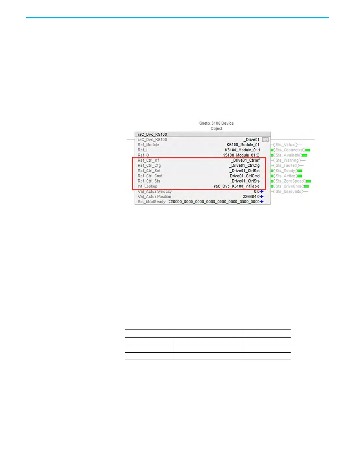
When the Device Object Add-On Instruction is created, it references Data
Types that interface with the drive to exchange command and status
information. You must create each Device Object Add-On Instruction as a
unique instance.
Figure 257 - Device Object
raC_UDT_Itf_K5100_Cfg
raC_UDT_Itf_K5100_Cfg is the Power Motion Common Control Interface
User-Defined Data Type for device configuration. Its members provide
selection between drive units (counts) or user units (PU).
This selection is very useful because the Kinetix 5100 drive natively supports
only drive units. When the Operating Units = 1, the Motion Resolution and
ConversionConstant values are used. Position Scaling originates from the
KNX5100C software and is used together with the Cfg tags to derive user
scaling units.
Example Configuration with Position Units
The E-Gear ratio (KNX5100C>Function List>E-Gear Ratio) is always used to
provide a representation of positioning (units or counts) or to define a Pulse-
Pulse Following relationship (MAG/PT). When the E-Gear ratio is changed, the
positioning of the drive is changed. When not using the MAG Add-On
Instruction or PT operation mode, the E-Gear ratio is used to define position
scaling.
Table 152 - raC_UDT_Itf_K5100_Cfg Data Types
Member Description DataType
OperatingUnits 0 = Drive Units; 1 = UserUnits DINT
MotionResolution Motion Counts per Motor Revolution DINT
ConversionConstant Motion Counts per Position Unit REAL

 Loading...


