86 Rockwell Automation Publication 2198-UM004D-EN-P - December 2022
Chapter 4 Connect the Kinetix 5100 Drive System
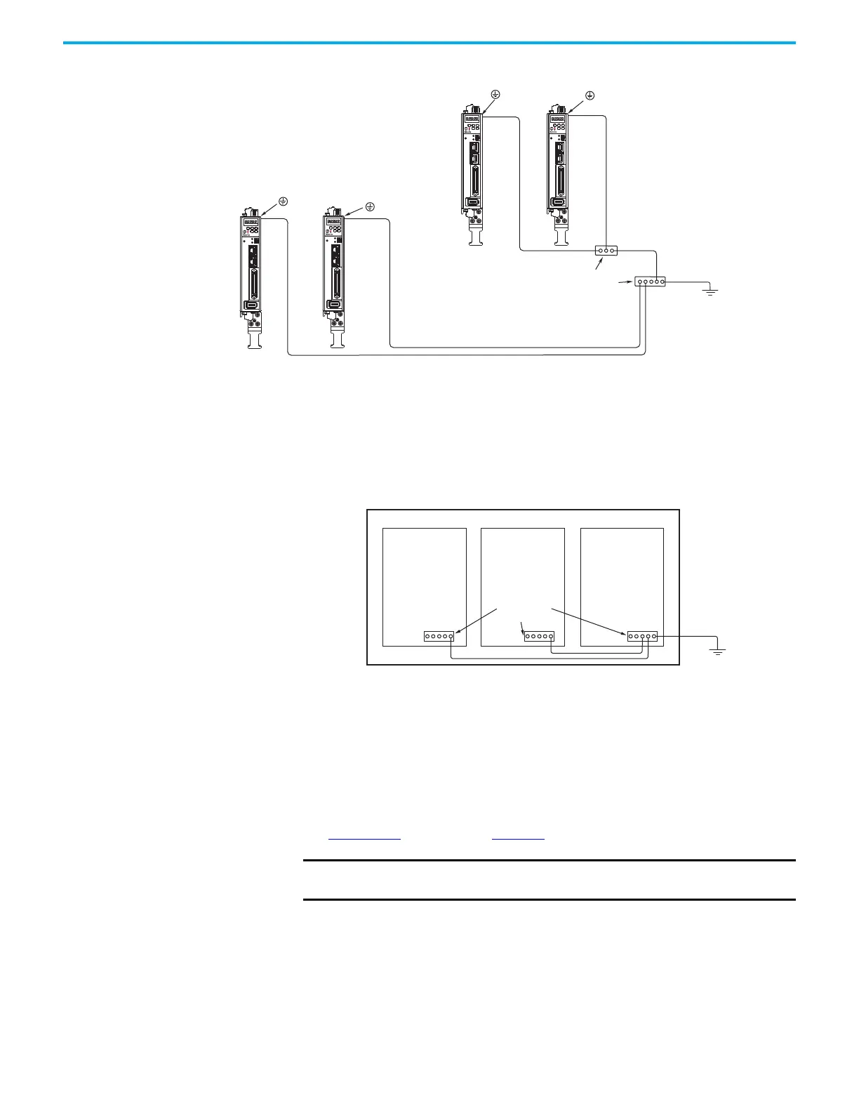
Figure 53 - Chassis Ground Configuration (multiple Kinetix 5100 drives on one panel)
Ground Multiple Subpanels
In this figure, the chassis ground is extended to multiple subpanels.
Figure 54 - Subpanels Connected to a Single Ground Point
Wiring Requirements Wire must be copper with 75 °C (167 °F) minimum rating. Phasing of main AC
power is arbitrary and earth ground connection is required.
See Appendix
A beginning on page 457 for interconnect diagrams.
2
1
I/0
AUX
5100
NET
MOD
CHARGE
2
1
I/0
AUX
5100
NET
MOD
CHARGE
2
1
I/0
AUX
5100
NET
MOD
CHARGE
2
1
I/0
AUX
5100
NET
MOD
CHARGE
Bonded Cabinet
Ground Bus
Ground Grid or Power
Distribution Ground
Always follow NEC and
applicable local codes.
Chassis Ground
Chassis Ground
Chassis Ground
Chassis Ground
Make braided ground straps with at least
10 mm
2
(0.0155 in
2
) cross-sectional area.
Keep straps as short as possible.
Always follow NEC and
applicable local codes.
Ground Grid or Power
Distribution Ground
Bonded Ground
Bus
IMPORTANT
The National Electrical Code and local electrical codes take precedence
over the values and methods provided.

 Loading...


