338 Rockwell Automation Publication 2198-UM004D-EN-P - December 2022
Chapter 11 Motion Control in PR Mode
Index Position Command Operation
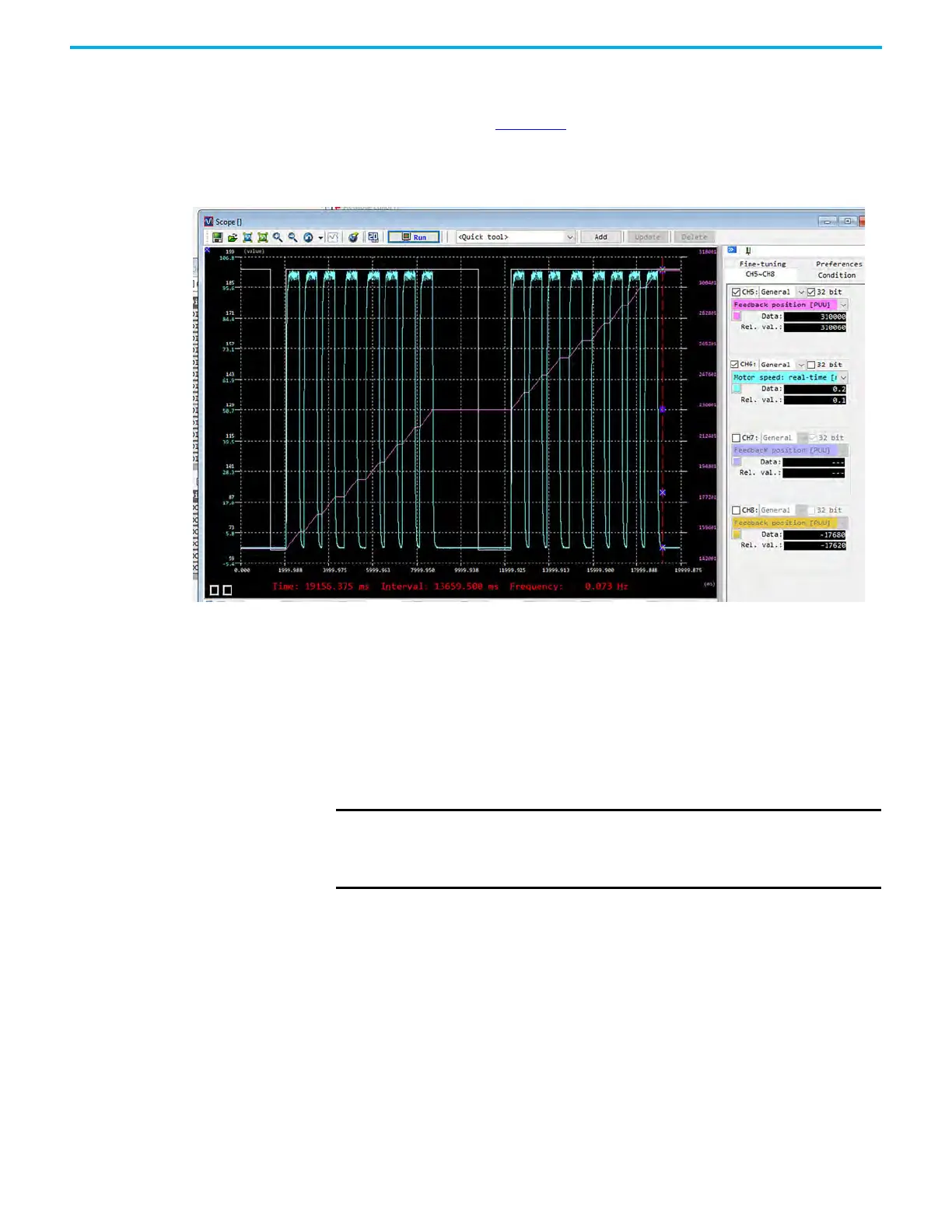
In the scope tracing in Figure 146, the blue pen is motor rpm and the pink pen
is motor feedback position.
Figure 146 - Index Position Command Operation
When executing the indexes (in this example, PR#01…PR#-08) the motor must
be homed before executing the indexes. The indexes move forward for 8
separate indexes, when it is complete, you can restart the sequence by setting
Command Triggered DI signal. This Scope trace shows two sequences by using
the Index Position instructions. In summary, the benefit to using this system
is that the absolute positioning can occur with repetitive indexes, without
having to re-calculate absolute targets. This system provides a 'quasi' rotary
mode of operation.
IMPORTANT The indexing coordinate system may not reflect actual motor counts,
because its absolute range is persistent through the natural rollover of
the motor feedback. For this reason, it is not considered a true rotary
unwind.

 Loading...


