Rockwell Automation Publication 2198-UM004D-EN-P - December 2022 475
Appendix A Interconnect Diagrams
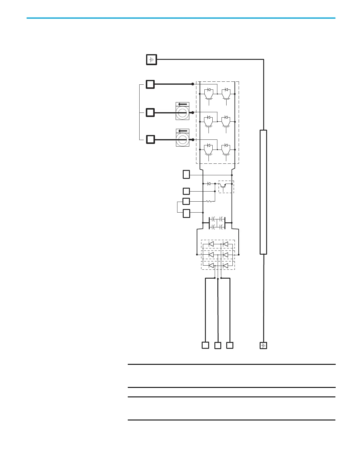
System Block Diagram This power block diagram applies to all 2198-Exxxx-ERS servo drives.
Figure 255 - Power Block Diagram
L1
L2
L3
WV
U
ESH
DC–
DC+
DC
–
DC+
ISH
Chassis
Shunt/DC-bus Connector
Shunt
Transistor
Internal
Shunt
Resistor
Inverter Section
Three-phase Motor Output
IMPORTANT Only 2198-E1004-ERS, 2198-E1007-ERS, 2198-E1015-ERS, 2198-E1020-ERS,
2198-E2030-ERS, 2198-E4004-ERS, 2198-E4007-ERS, and 2198-E4015-
ERS drives have an internal shunt and ISH terminal.
IMPORTANT Only 2198-E1004-ERS, 2198-E1007-ERS, 2198-E1015-ERS, and
2198-E1020-ERS drives support both single-phase and three-phase
operation.

 Loading...


