Rockwell Automation Publication 2198-UM004D-EN-P - December 2022 253
Chapter 10 Modes of Operation
This table shows the binary weighting representation:
Control Structure of Torque Mode
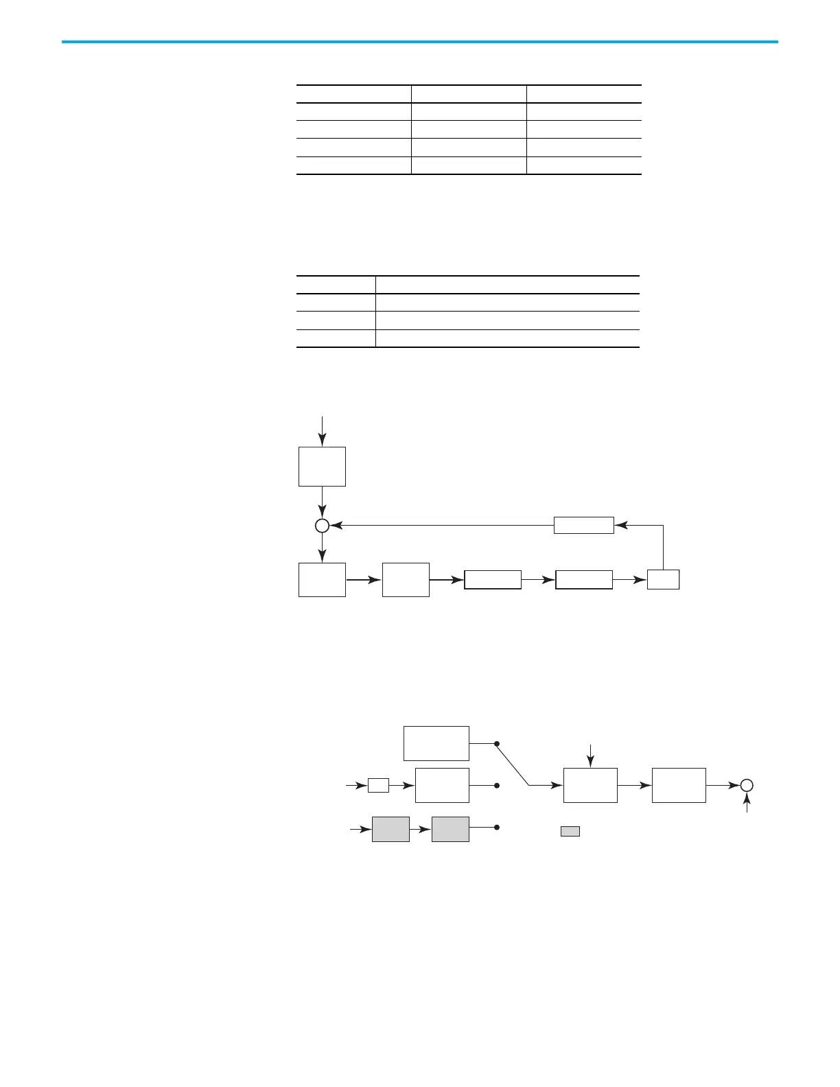
The following diagram shows the basic control structure of torque mode:
The torque command unit is to specify the torque command source, including
the parameter Analog Voltage Scaling ID148 (P1.041) and S-curve setting. The
torque control unit manages the gain parameters of the servo drive and
calculates the current for servo motor in time; this can only set by commands.
The structure of a torque command unit is as follows.
The upper path is the command from the preset torque register, while the
middle path is the external analog command. The command is selected
according to the status of the DI.TCM0 and DI.TCM1 signals, and with the
Operation Mode set to T or Tz.
The lower path is used when the operation mode is IO mode. The intention is
to use the raC_xxx_K5100_MAT add-on instruction.
Torque Command TCM0 TCM1
Analog Input Torque 0 0
Torque Register 1 0 1
Torque Register 2 1 0
Torque Register 3 1 1
Table 91 - Relevant Parameters
Parameter Name
ID117 (P1.001) ControlMode
ID123 (P1.007) TorqueCmdLowPassFilterTime
ID148 (P1.041) AnalogToTorqueScale
Motor
Current Loop
Speed
Control
Command
Speed
Command
Processing
Resonance
Suppression
Current Sensor
Torque Limit
S
p
e
e
d
C
o
m
m
a
n
d
P
r
o
c
e
s
s
i
n
g
S
p
e
e
d
C
o
m
m
a
n
d
C
u
r
r
e
n
t
S
e
n
s
o
r
S
p
e
e
d
C
o
n
t
r
o
l
R
e
s
o
n
a
n
c
e
S
u
p
p
r
e
s
s
i
o
T
o
r
q
u
e
L
i
m
i
t
C
u
r
r
e
n
t
L
o
o
p
M
o
t
o
r
Analog Voltage
Scaling
ID148 (P1.041)
A/D
Register
ID116 …ID118
(P1.012…P1.014)
Command
Selection
ID117 (P1.001)
Low-pass
Filter
ID123 (P1.007)
I/O Connector DI.TCM0, DI.TCM1 signal
Torque
Ramp Time
Torque
Reference
I/O Mode - Torque
Analog Signal
= I/O Assembly Output Parameter

 Loading...


