470 Rockwell Automation Publication 2198-UM004D-EN-P - December 2022
Appendix A Interconnect Diagrams
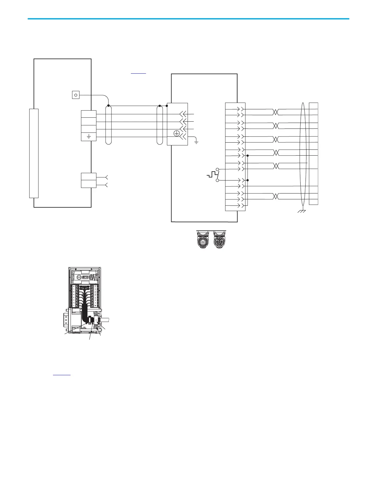
Kinetix 5100 Servo Drive
and Linear Actuator Wiring
Examples
These compatible linear actuators have separate connectors and cables for
power/brake and feedback connections.
Figure 250 - Kinetix 5100 Drives with Kinetix LDAT Linear Thrusters
U
V
W
D+
D-
1
2
4
3
2
1
Brown
Black
Blue
Green/Yellow
Shield
1
2
3
4
5
6
7
8
9
10
11
12
13
14
15
GND
AM+
AM-
BM+
BM-
IM+
IM-
+5VDC
ECOM
WHITE/BLUE
GREEN
WHITE/GREEN
GRAY
WHITE/GRAY
BLACK
WHITE/BLACK
RED
WHITE/RED
1
2
3
4
5
10
14
6
12
S1
–
TS
ORANGE
WHITE/ORANGE
11
S2
S3
YELLOW
WHITE/YELLOW
13
8
3
4
5
6
1
2
14
15
16
17
12
11
13
9
10
COM
U
V
W
C
B
A
D
Universal Feedback
(UFB) Connector
Motor Power
(MP) Connector
Motor Feedback
(MF) Connector
Three-phase
Motor Power
Motor
Feedback
Thermostat
Refer to table on page 457
for note
Cable Shield
Clamp
Note 11
Power Connector
Feedback Connector
SpeedTec DIN
Motor Connectors
2090-CFBM7DF-CEAAxx (standard) or
2090-CFBM7DF-CEAFxx (continuous-flex)
(flying-lead) Feedback Cable
Note 13
2090-CPWM7DF-xxAAxx
(standard) or
2090-CPWM7DF-xxAFxx
(continuous-flex)
Motor Power Cable
Notes 13, 17
Refer to feedback kit
illustrations (lower left)
for proper grounding
technique.
2198-Exxx -ERSx
Kinetix 5100 Drives
See the Kinetix 5100 Feedback Connector Kit Installation Instructions,
publication 2198-IN019
, for connector kit specifications.
LDAT-Sxxxxxx-xBx
Linear Thrusters with
Incremental Feedback
2198-K51CK-D15M Feedback
Connector Kit
2198-K51CK-D15M
Feedback Connector Kit
Ground Technique for
Feedback Cable Shield
360° exposed shield that is secured
under clamp.
Clamp Screws (2)
Clamp
Tie Wrap

 Loading...


