48 Rockwell Automation Publication 2198-UM004D-EN-P - December 2022
Chapter 2 Plan and Install the Kinetix 5100 Drive System
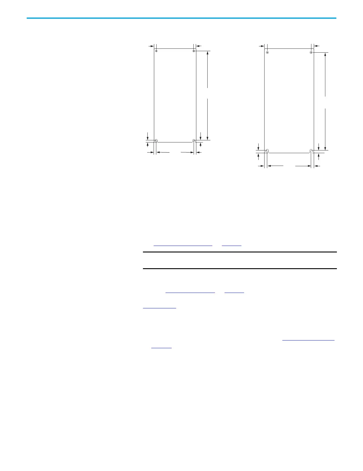
Figure 17 - Mounting-hole Dimensions (continued)
Mount the Drive
Follow these steps to mount your Kinetix 5100 drive.
1. Lay out the position for the Kinetix 5100 drive and accessories in the
enclosure.
See Establish Noise Zones
on page 43 for panel layout recommendations.
2. Drill holes in the panel for mounting your servo drive.
Refer to Drill-hole Patterns
on page 47. For drive dimensions, see the
Kinetix Servo Drives Specifications Technical Data, publication
KNX-TD003
.
3. Loosely attach the servo drive to the panel.
The recommended mounting hardware is M4 (#8-32) steel machine
screws. Observe bonding techniques as described in HF Bond the Drives
on page 40
.
4. Tighten all mounting fasteners.
5. Apply 2.0 N•m (17.7 lb•in) maximum torque to each fastener.
125
(4.92)
297
(11.69)
7.0
(0.28)
8.0
(0.31)
366
(14.41)
164
(6.46)
11.0
(0.43)
10.0
(0.39 )
8.0
(0.31)
8.0
(0.31)
8.0
(0.31)
11.0
(0.43)
11.0
(0.43)
11.0
(0.43)
7.0
(0.28)
10.0
(0.39 )
2198-E2075-ERS
2198-E4075-ERS
Kinetix 5100 Drive
2198-E2150-ERS
2198-E4150-ERS
Kinetix 5100 Drive
Dimensions are in mm (in.)
IMPORTANT
To improve the bond between the Kinetix 5100 drive and subpanel,
construct your subpanel out of zinc-plated (paint-free) steel.

 Loading...


