72 Rockwell Automation Publication 2198-UM004D-EN-P - December 2022
Chapter 3 Connector Data and Feature Descriptions
Kinetix 5100 400V-class drives require 21.6…26.4V DC (24v, nom) input control
power.
Feedback Specifications The Kinetix 5100 drive uses the MFB connector for various types of motor
feedback. The AUX connector uses TTL incremental feedback only.
Use the 2198-K51CK-D15M feedback connector kit for terminating feedback
conductors when building your own cables.
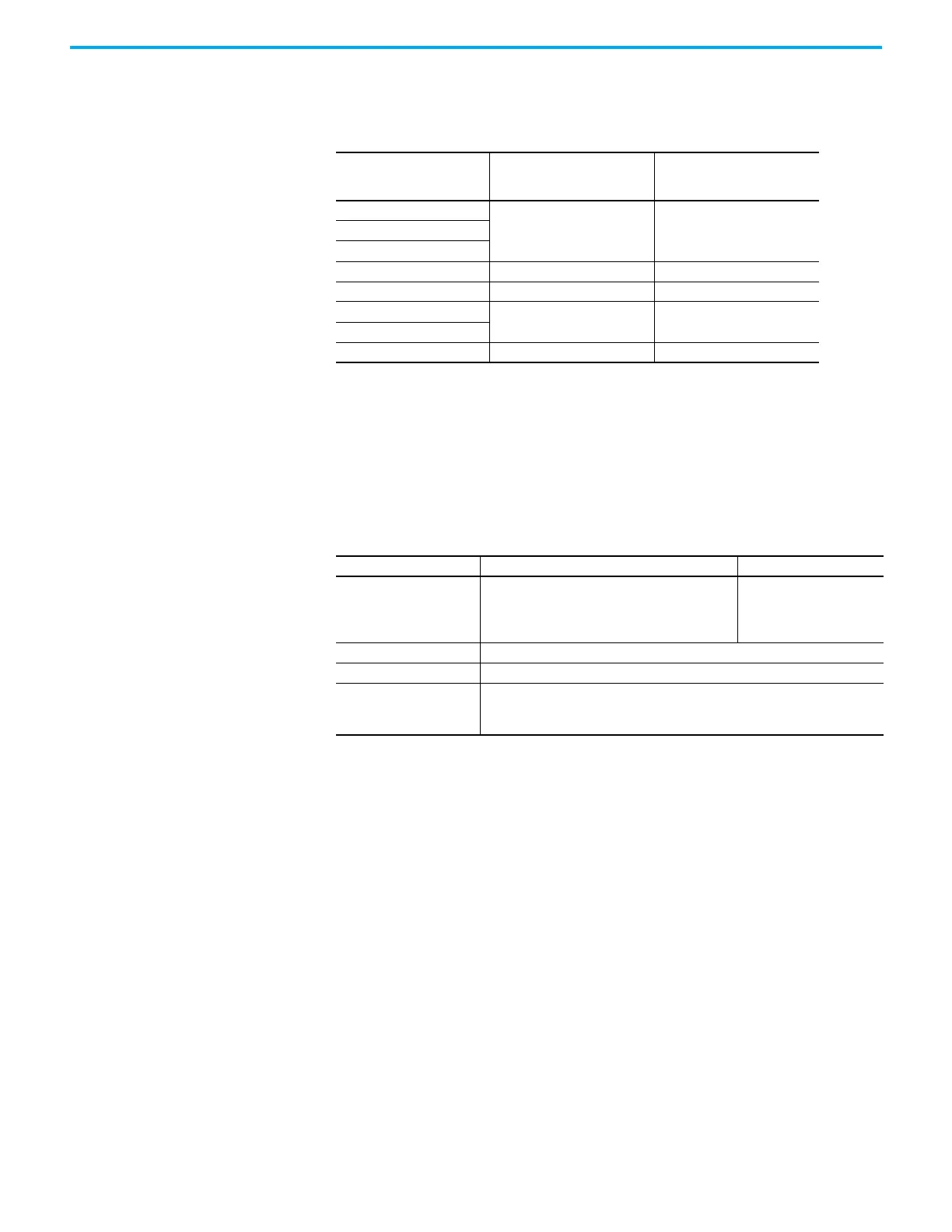
Table 32 - Control Power Specifications - 400V-class Drives
Cat. No.
Maximum Input Current of
Control Power
A rms at 24V DC
Inrush current of Control
Power
A at 24V DC
2198-E4004-ERS
1.27 4.142198-E4007-ERS
2198-E4015-ERS
2198-E4020-ERS 1.40 4.97
2198-E4030-ERS 1.77 4.97
2198-E4055-ERS
2.03 3.24
2198-E4075-ERS
2198-E4150-ERS 4.43 3.40
Table 33 - Feedback General Specifications
Attribute Motor Feedback Auxiliary Feedback
Feedback device support
• Nikon (24-bit) serial (Kinetix TLP motors)
•Hiperface
• Tamagawa (17-bit) serial (Kinetix TL/TLY motors)
• Digital AqB with or without UVW, incremental
Digital AqB incremental
Power supply (EPWR5V) 5.09…5.41V, 300 mA, max
Power supply (EPWR9V) 8.3…9.9V, 150 mA, max
Motor thermostat
Single-ended input:
•Under 500 Ω = No Fault
•Over 10 kΩ = Fault

 Loading...


