68 Rockwell Automation Publication 2198-UM004D-EN-P - December 2022
Chapter 3 Connector Data and Feature Descriptions
Motor Brake Circuit
The brake option is a motor mounted spring-set holding brake that releases
when voltage is applied to the brake coil in the motor. The customer-supplied
24V power supply drives the brake output through a relay.
Wire the Brake Control Circuit
One digital output can be used for motor brake control. In this example,
OUTPUT6 is used. Wire the brake control circuit according to the appropriate
interconnect diagram in Kinetix 5100 Drive/Rotary Motor Wiring Examples
beginning on page 464
. An external customer-supplied 24V power supply is
required.
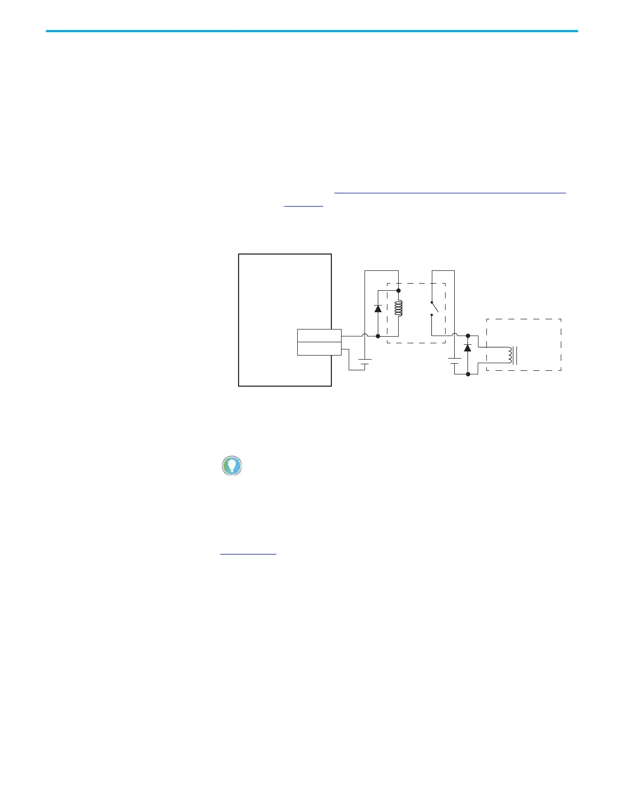
Figure 39 - Brake Control Circuit Example
(1) Customer-supplied diode or MOV suppression device.
An example brake circuit contains the following components:
• Digital output 40 mA (max) continuous current.
• Relay 700-HK36Z24 with DIN mount 700-HN121 or equivalent
• Suppression device examples include 1N4004 diode,
Bulletin 199-MSMV1 MOV, or equivalent
See Kinetix Rotary Motion Specifications Technical Data, publication
KNX-TD001
, for coil current ratings and brake response times.
46
40
OUTPUT6+
OUTPUT6–
BR+
BR–
2198-Exxxx-ERS
Kinetix 5100 Servo Drive
I/O Connector with
2198-TBIO Expansion Block
Relay
Motor Brake
Connections
Customer Supplied
+24V DC
Servo Motor
(1)
(1)
Choose a relay rated for 40 mA continuous current or less.

 Loading...


