74 Rockwell Automation Publication 2198-UM004D-EN-P - December 2022
Chapter 3 Connector Data and Feature Descriptions
Auxiliary Feedback Specifications
The Kinetix 5100 drives support TTL incremental feedback devices on the
10-pin auxiliary feedback connector (AUX). See Table 38
on page 74 for Digital
AqB encoder feedback specifications.
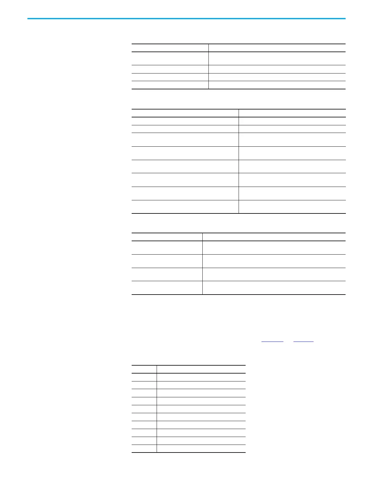
Table 40 - Auxiliary Feedback Signals by Device Type
Table 37 - Tamagawa Serial Specifications
Attribute Value
Encoder nonvolatile memory usage
Programmed with TL-Axxxx-B and TLY-Axxxx-B motor data as
Allen-Bradley memory format.
Differential input voltage 1.0…7.0V
Data communication 2.5 Mbps, 8 data bits, no parity
Battery 3.6V, ER14252 or equivalent, 1/2AA size
Table 38 - Generic TTL Encoder Feedback Specifications
Attribute Value
TTL incremental encoder support 5V, differential A quad B
Quadrature interpolation 4 counts / square wave period
Differential input voltage
(MTR_AM, MTR_BM, and MTR_IM)
5V DC, differential line driver (DLD) output compatible
DC current draw
(MTR_AM, MTR_BM, and MTR_IM)
30 mA, max
Input signal frequency
(MTR_AM, MTR_BM, and MTR_IM)
5.0 MHz, max
Edge separation
(MTR_AM and MTR_BM)
42 ns min, between any two edges
Commutation verification
Commutation angle verification performed at the first
Hall signal transition and periodically verifies thereafter
Hall inputs
(MTR_S1, MTR_S2, and MTR_S3)
Single-ended, TTL, open collector, or none
Table 39 - Generic Sine/Cosine Incremental Specifications
Attribute Value
Input frequency
(MTR_SIN and MTR_COS)
250 kHz, max
Differential input voltage
(MTR_SIN and MTR_COS)
0.6…1.2V, peak to peak
Commutation verification
Commutation angle verification performed at the first Hall signal transition
and periodically verifies thereafter.
Hall inputs
(MTR_S1, MTR_S2, and MTR_S3)
Single-ended, TTL, open collector, or none.
Pin Digital AqB Incremental
1 AUX_AM+
2 AUX_AM-
3 AUX_BM+
4 AUX_BM-
5 AUX_IM+
6 AUX_IM-
7 AUX_ECOM
8 AUX_EPWR5V
9 Reserved
10 Reserved

 Loading...


