56 Rockwell Automation Publication 2198-UM004D-EN-P - December 2022
Chapter 3 Connector Data and Feature Descriptions
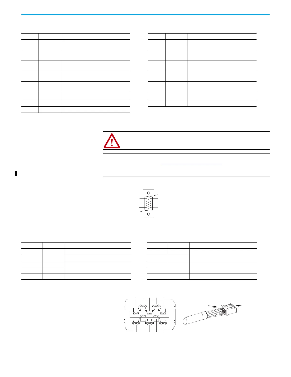
Figure 24 - Pin Orientation for 15-pin Motor Feedback (MFB) Connector
Auxiliary Feedback Connector Pinout
Figure 25 - Pin Orientation for Auxiliary Feedback (AUX) Connector
Table 22 - Motor Feedback (MFB) Connector Pinout
MFB Pin Signal Description MFB Pin Signal Description
1
SIN+
AM+
Sine differential input+
AM+ differential input+
9– Reserved
2
SIN–
AM–
Sine differential input–
AM– differential input–
10
DATA–
IM–
Data differential input –
Index pulse–
3
COS+
BM+
Cosine differential input+
BM+ differential input+
11 TS
Motor thermal switch (normally closed)
(1)
4
COS–
BM–
Cosine differential input–
BM– differential input–
12 S1 Single-ended 5V Hall effect commutation
5
DATA+
IM+
Data differential input +
Index pulse+
13 S2 Single-ended 5V Hall effect commutation
6 ECOM Common 14
EPWR_5V
(2)
Encoder power (+5V)
7
EPWR_9V
(2)
Encoder power (+9V) 15 – Reserved
8 S3 Single-ended 5V Hall effect commutation
(1) Not applicable unless motor has integrated thermal protection.
(2) Determine which power supply your encoder requires and connect to only the specified supply. Do not make connections to both.
ATTENTION: The motor feedback will determine which encoder power
source is used. Be sure you use the correct power source for your encoder
to avoid equipment damage.
IMPORTANT
For the maximum length of the drive to motor power and feedback
cable, see Maximum Cable Length
on page 95. System performance
was tested at these specifications and also applies when meeting CE
and UK requirements.
Pin 11
Pin 6
Pin 15
Pin 1
Pin 10
Pin 5
Pin Signal Description Pin Signal Description
1 AM+ Channel A Differential Input + 6 IM– Channel Index Differential Input -
2 AM– Channel A Differential Input - 7 ECOM Encoder Common
3 BM+ Channel B Differential Input + 8 EPWR5V Encoder 5V Power Output
4 BM– Channel B Differential Input - 9 Reserved Reserved
5 IM+ Channel Index Differential Input + 10 Reserved Reserved
View from rear of
connector kit.
Soldered Pins
Front of
Connector Kit

 Loading...


