Rockwell Automation Publication 2198-UM004D-EN-P - December 2022 437
Chapter 15 Programming via Drive Parameters
Description of Digital Output
Functions
The Kinetix 5100 drive provides six physical digital outputs. These digital
outputs are primarily configured in KNX5100C software from
Function List>Settings>Digital IO/Jog Control.
You can force these outputs (when the drive is online and the Enable DO
Override is checked) to be On or Off.
In the Digital Input dialog box, Status represents the logical level of the output.
The available digital output functions are listed in the following table.
0x45
Disable External pulse
When using PT Operation mode and this DI is on, the drive stops responding to commands using external pulses.
The motor does not move while this DI is on. This function only works when configured with DI8.
Level triggered PT
0x46
Stop
When this DI is on, the drive decelerates the motor. AutoProtectionDecelTime ID 296 (P5.003) is used to define the
deceleration profile. This DI only stops PR command types (including positioning and constant velocity; Jog). This
command does not stop Jog commands (outside of a PR command) or E-CAM commands.
Rising-edge triggered,
level triggered
PR
0x47
Profile Quick Stop
When this DI is on, the drive decelerates and disables the motor. AutoProtectionDecelTime ID 296 (P5.003) is used to
define the deceleration profile. If a holding brake is used, this stop uses any configured brake timing. This stop
issues alarm: A35F when its complete.
Rising-edge triggered PT, PR, T, S
0x48
Servo On with holding brake
Use this DI when a holding brake is used. When this DI is on, the drive is activated (Servo On). When this DI is off, the
drive decelerates and disables the motor. AutoProtectionDecelTime ID 296 (P5.003) STP is used to define the
deceleration profile. This DI is used with Vertical Load Control and this DI setting uses any configured brake timing.
Always configure this DI as N.O.
Level triggered All except I/O
Table 135 - Digital Inputs (Continued)
Setting DI Description Trigger Method Control Mode
Table 136 - Relevant Parameters
Parameter Name
ID203 (P2.018) DO1Configuration
ID204 (P2.019) DO2Configuration
ID205 (P2.020) DO3Configuration
ID206 (P2.021) DO4Configuration
ID207 (P2.022) DO5Configuration
ID225 (P2.041) DO6Configuration
Table 137 - Digital Outputs
Setting DO Description Triggering Method Control Mode
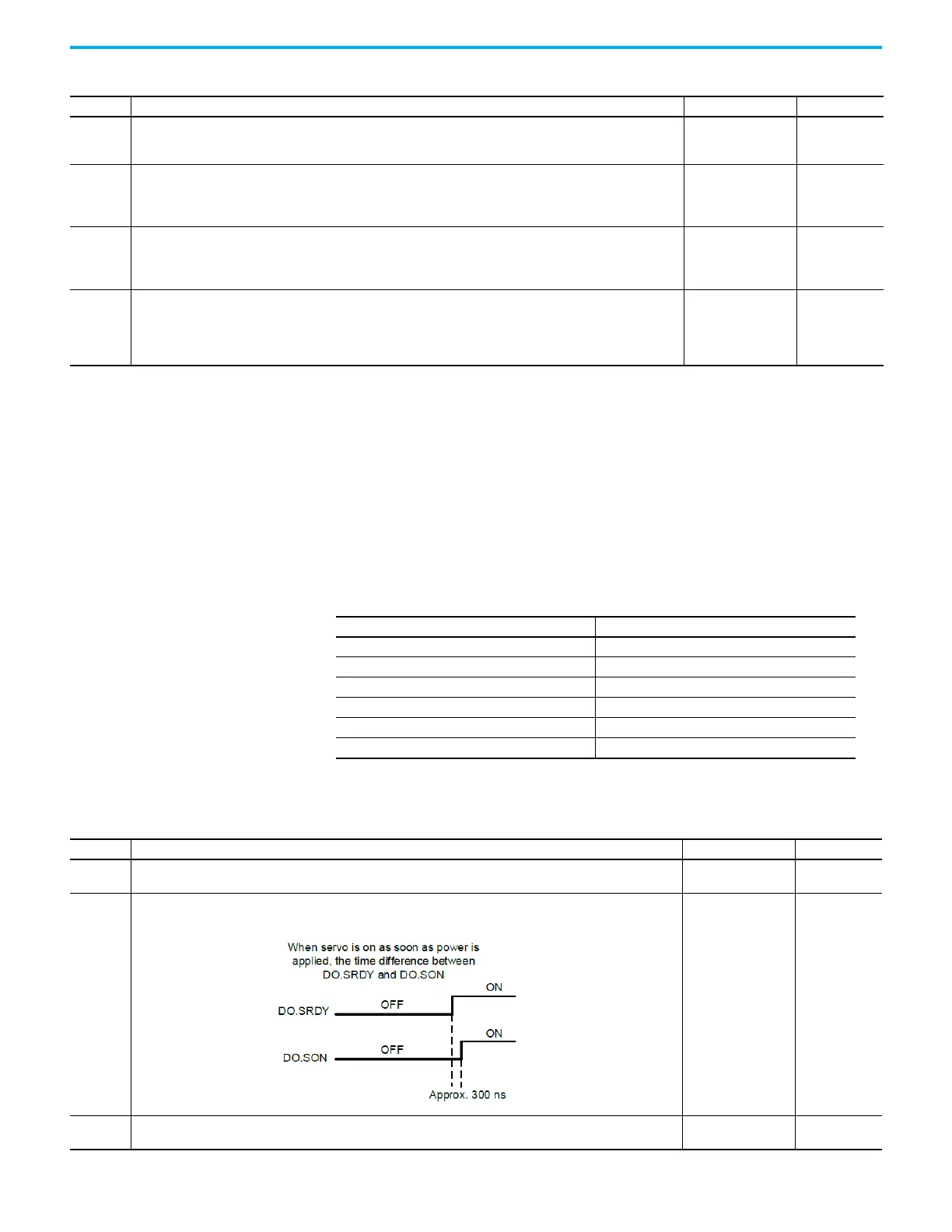
0x01
Servo Ready
This DO is on when both the control and main power is applied to the drive and the drive is not faulted.
Level triggered All
0x02
Servo On
This DO is on when the servo is activated (enabled) and the drive is not faulted.
Level triggered All
0x03
Motor is at zero speed
This DO is on whenever the motor is within the ZeroSpeedWindow ID145 (P1.038).
Level triggered All

 Loading...


