150 Rockwell Automation Publication 2198-UM004D-EN-P - December 2022
Chapter 7 Configure the Drive with KNX5100C Software
For example:
By using the KNX5100C software, choose
Start>Parameter Editor>Motor>CommutationOffset (ID 602, (PM.007)).
With Motor Offset selected as the commutation alignment, the parameter
ID602 (PM.007) CommutationOffset is 11.2°.
Therefore, the Commutation Offset setting for the Drive Offset type must be in
the range of 0…96.2° and 286.2…360°.
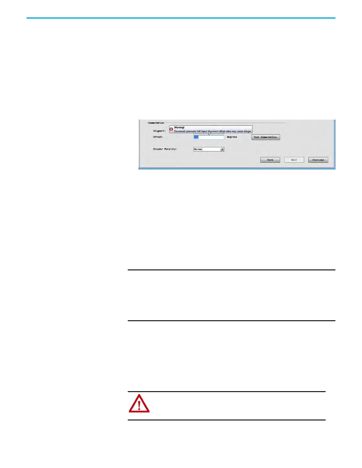
If you click Download and the input value of 200 exceeds the range, the
following warning appears.
You must change the input value before you can click Download again and
have the input value accepted.
Run a Commutation Test
The commutation test determines an unknown commutation offset and can
also be used to determine (or verify) the polarity of the start-up commutation
wiring.
You can choose to keep or discard the test results.
The following parameters are updated after commutation test:
• Phase Sequence ID601 (PM.006)
• Commutation Offset ID602 (PM.007)
• Hall Hysteresis Width ID603 (PM.008)
To test commutation, perform the following steps.
1. Uncouple the motor from the load.
IMPORTANT
This test mainly applies to third-party or custom permanent-magnet
motors equipped with (TTL with Hall) incremental encoders that are
not available as a catalog number in the Motion Database.
This test also applies to Kinetix MP and Kinetix TLP motors that are
available as a catalog number in the Motion Database, and use to
verify a known commutation offset or use the test result other than
the commutation offset specified in the motion Database.
ATTENTION: To avoid personal injury or damage to equipment, you
must uncouple the motor from each load you test as uncontrolled
motion can occur if an axis with an integral motor brake is released
during the test.

 Loading...


