Rockwell Automation Publication 2198-UM004D-EN-P - December 2022 151
Chapter 7 Configure the Drive with KNX5100C Software
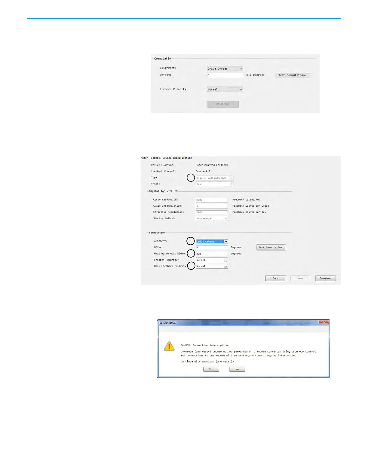
2. In the Alignment field, select Drive Offset.
Different encoder types result in different configuration fields.
3. Type an offset.
4. If the attached motor feedback type is Digital AqB with UVW (A in the
following figure) and the Commutation Alignment is Drive Offset (B),
then you must add additional data to the Hall Hysteresis Width
(C) and
Hall Feedback Polarity (D) fields.
5. Click Test Commutation.
After you click Test Commutation, the following message appears to alert
you that this operation resets the drive.
6. Click Yes.
A message window alerts you that the process might take some time to
complete.
When the process is complete, a results window appears with suggested
parameter values.

 Loading...


