Rockwell Automation Publication 2198-UM004D-EN-P - December 2022 185
Chapter 7 Configure the Drive with KNX5100C Software
Configuration and Status of Digital Input (DI) and Digital Output (DO)
Signals
In the Digital Input (DI) and Digital Output (DO) sections, the user defined
signals are shown with their individual configurations.
If the contact type of the DI or DO signal is normally closed, 'NC' is added at
the end of the signal name. Click ‘Edit DIO Configurations’ to change the
configuration of the signal.
The Status column shows the status of the digital I/O. This is the LOGICAL
level of the input that is based on the use of N.O. or N.C. This is NOT the actual
voltage on the terminals (0V DC = OFF, 24V DC = ON).
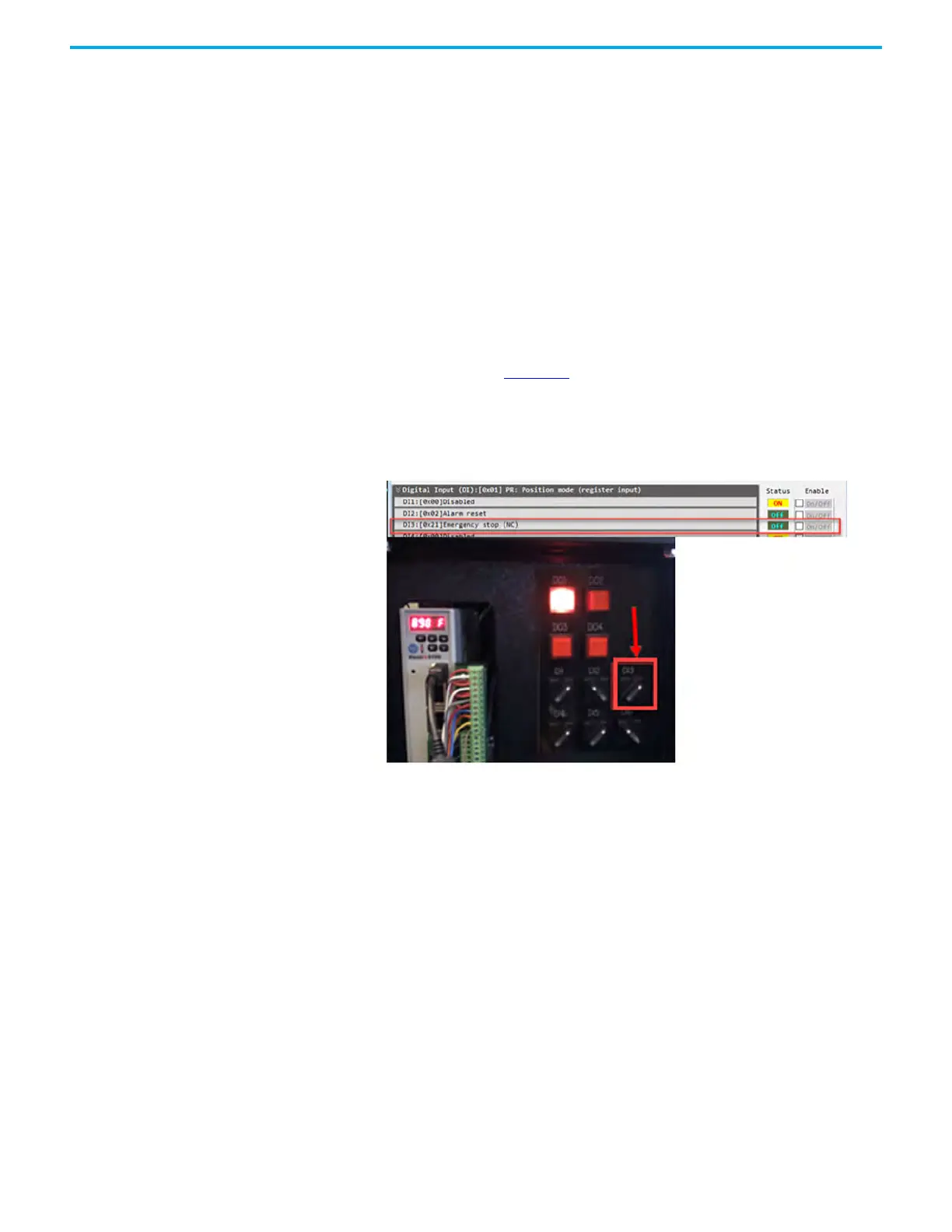
An example is shown in Figure 82
. DI3 is configured as an N.C. input. The
demo box has DI3 toggle switch ON (24V DC to the input). Notice that the
Status in the Control Panel is Off. This is because the configuration is NC, the
drive interprets (and expects) this state/condition as being OFF.
Figure 82 - Status Example
This dialog box also shows the On/Off status of the DI or DO signals and offers
manual control of the DI or DO signal state. This control is useful when testing
or troubleshooting the signals.

 Loading...


