Rockwell Automation Publication 2198-UM004D-EN-P - December 2022 65
Chapter 3 Connector Data and Feature Descriptions
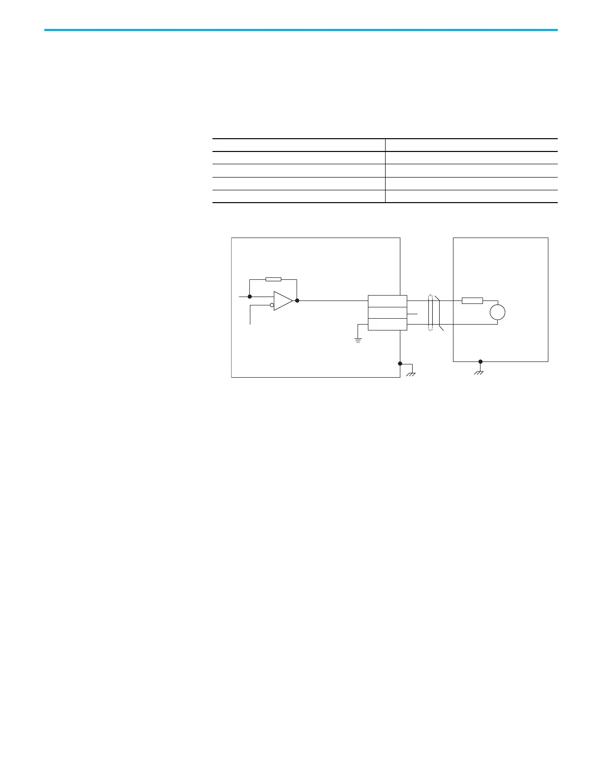
Analog Outputs
There are two analog outputs, AOUT1 and AOUT2, available on the I/O
connector. Assignments are changed via KNX5100C software > Function List >
Analog IO > Output Monitor.
Figure 35 - Analog Output Circuitry
Buffered Encoder Outputs
Encoder output signals can be connected to the receiving device with line
receiver (differential) or
opto-coupler isolated inputs. The encoder output
signals are flexible. The signals are scaled and programmed by using
KNX5100C software > Function List > Pulse Output.
Table 29 - Analog Output Specifications
Parameter Description
Analog outputs voltage –8V… +8V DC or -10V…+10VDC, user configurable
Analog outputs resolution 10 bits, min
Analog outputs current 1 mA, max
Analog outputs scan time 0.25 ms, max
AGND
24 kΩ
Output:
1 mA, max
8 kΩ
8V
Full-scale
V
13
16
15
AOUT1
AOUT2
Analog GND
Servo Drive
Controller
I/O Connector with
2198-TBIO Expansion Block

 Loading...


