110 Rockwell Automation Publication 2198-UM004D-EN-P - December 2022
Chapter 4 Connect the Kinetix 5100 Drive System
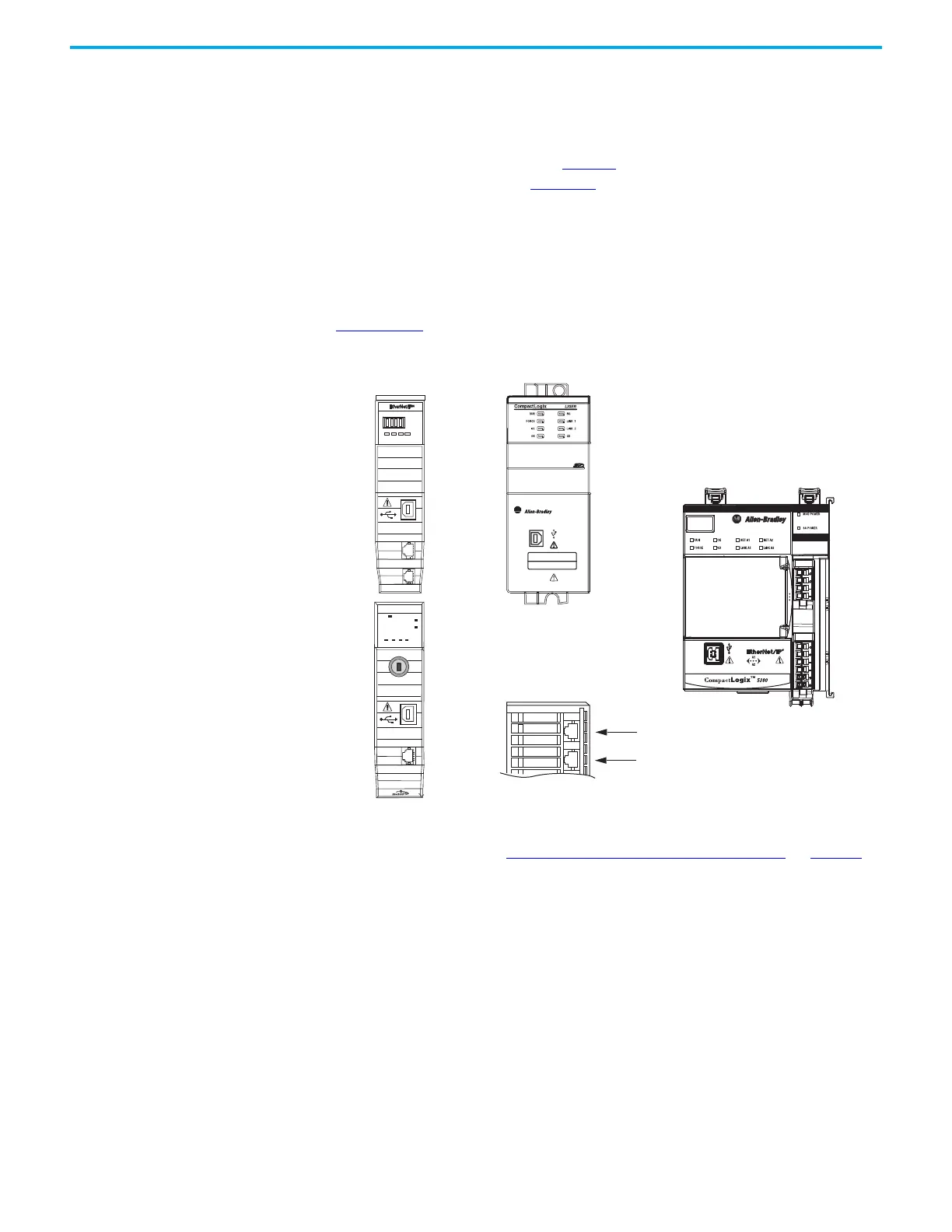
Ethernet Cable Connections This procedure assumes that you have your Logix 5000™ controller and
Kinetix 5100 drives mounted and are ready to connect the network cables.
The EtherNet/IP™ network is connected by using the PORT 1 and PORT 2
connectors of the drive. Refer to page 50
to locate the Ethernet connectors on
your drive module. Refer to Figure 70
to locate the connectors on your Logix
5000 controller.
Shielded Ethernet cable is required for EMC compliance and is available in
several standard lengths. Ethernet cable lengths that connect drive-to-drive,
drive-to-controller, or drive-to-switch must not exceed 100 m (328 ft). Refer to
the Kinetix Motion Accessories Specifications Technical Data, publication
KNX-TD004
, for more information.
Figure 70 - ControlLogix and CompactLogix Ethernet Port Locations
The Logix 5000 controllers accept linear, ring (DLR), and star network
configurations. Refer to Typical Communication Configurations
on page 21
for linear, ring, and star configuration examples.
1 (Front)
2 (Rear)
00:00:BC:2E:69:F6
1
2
LNK1 LNK2NET OK
1
2
OKFORCE SDRUN
Logix5585
LINK
NET
TM
SAFETY ON
0000
ControlLogix 5570 Controller with
Bulletin 1756 EtherNet/IP Communication Module
ControlLogix Ethernet Ports
The 1756-EN2T modules have only one port,
1756-EN2TR and 1756-EN3TR modules have two.
Bottom View
Front Views
CompactLogix 5370 Controller,
Compact GuardLogix® 5370 Controller
(CompactLogix 5370 controller is shown)
Port 1, Front
Port 2, Rear
ControlLogix 5580 and
GuardLogix 5580 Controller
1 GB Ethernet Port
Front View
CompactLogix 5380 Controller, or
Compact GuardLogix 5380 Controller
(CompactLogix 5380 controller is shown)
Front View

 Loading...


