Rockwell Automation Publication 2198-UM004D-EN-P - December 2022 19
Chapter 1 Start
Typical Hardware
Configuration
Typical Kinetix 5100 drive systems include single-phase and three-phase
standalone configurations.
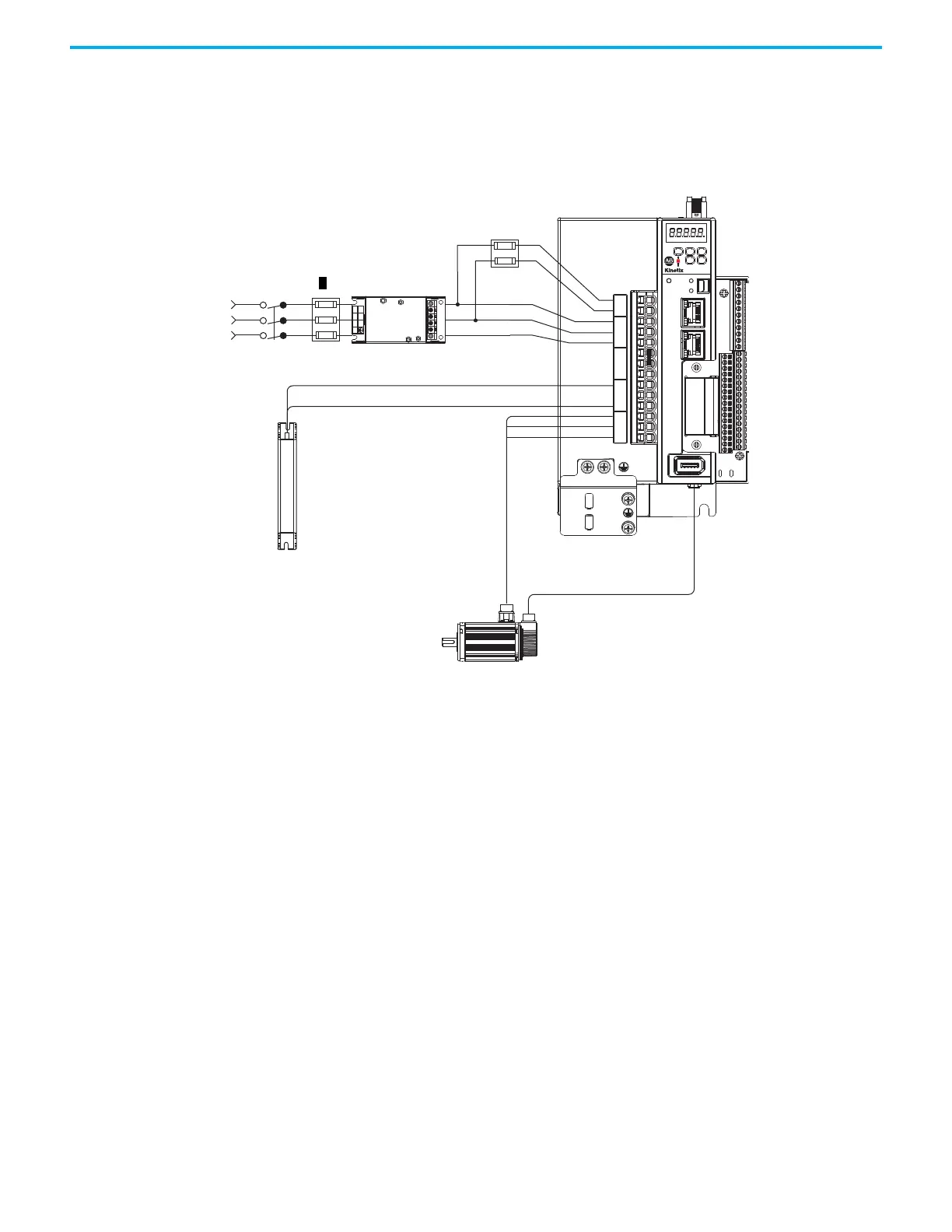
In this example, three-phase input power is applied to the Kinetix 5100 drive.
Figure 1 - Kinetix 5100 Standalone Drive with Three-phase Input Power
5100
2
1
NET
MOD
CHARGE
I/0
AUX
U
V
W
DC+
ISH
ESH
P1
P2
DC–
L1
L2
L3
L1C
L2C
L1 L2
L3
Kinetix 5100 Servo Drive
(2198-E1020-ERS drive is shown)
2198-DBx
xx-F
or 2198-DBRxx
x-F
AC Line Filter
(required for CE and UK)
Line
Disconnect
Device
Circuit
Protection
Three-phase
Input Power
Kinetix 2090
Motor Power Cable
2198-TBIO Terminal
Expansion Block
2198-Rxxx or 2097-Rx
Shunt Resistor
(optional equipment)
Ground Plate
for Motor Power
Ground Connection
Kinetix 2090
Motor Feedback Cable
Kinetix TLP
Servo Motor
Circuit
Protection

 Loading...


