Rockwell Automation Publication 2198-UM004D-EN-P - December 2022 71
Chapter 3 Connector Data and Feature Descriptions
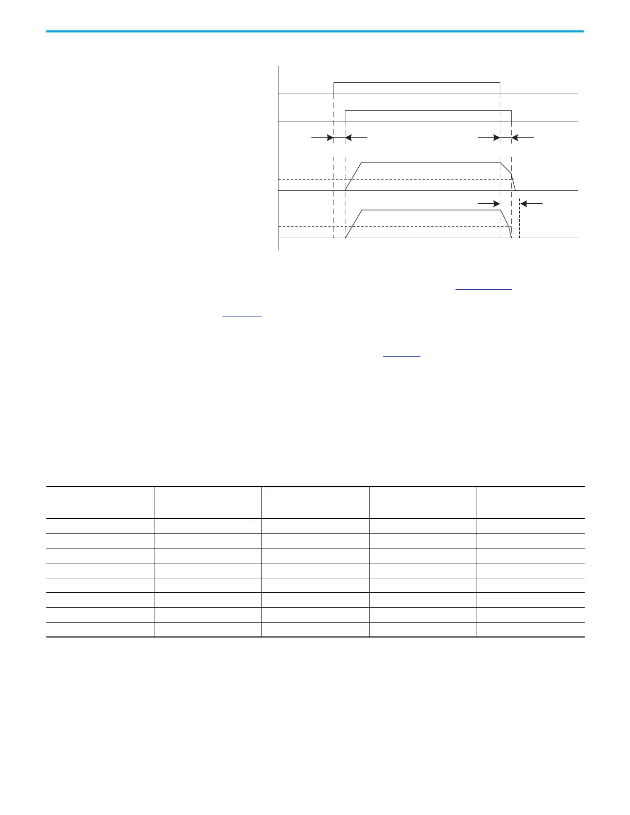
Figure 40 - Brake Control Timing Diagram
For motor brake specifications to size the interposing relay, see Kinetix Rotary
Motion Specifications Technical Data, publication KNX-TD001
. See the
interconnect diagram for your Kinetix 5100 drive/motor beginning on
page 464
for typical motor brake wiring.
More information on the Vertical Load Control setting (which populates
default brake settings) is found on page 161
.
Control Power
Kinetix 5100 200V-class drives require 95…132V AC (120V nom) single-phase,
with 120V AC input power or 170…253V AC (200…230V nom) single-phase, with
200…230V AC input power.
ON
ON
OFF
OFF
OFF
OFF
Servo On condition
Brake Output (DO)
ZSPD ID145 (P1.038)
Motor Speed (rpm)
Disengage Delay Time ID149 (P1.042)
Engage Delay Time ID150 (P1.043)
ZSPD ID145 (P1.038)
Motor Speed (rpm)
Engage Delay
Time ID150 (P1.043)
Scenario 1
Scenario 2
Servo On Condition
Brake Output (DO)
ZSPD ID145 (P1.038)
Motor Speed (rpm)
ZSPD ID145 (P1.038)
Motor Speed (rpm)
Disengage Delay Time ID149 (P1.042) Engage Delay Time ID150 (P1.043)
Engage Delay
Time ID150
(P1.043)
Table 31 - Control Power Specifications - 200V-class Drives
Kinetix 5100 (200V-class)
Drives Cat. No.
Input Current of Control Power
A rms at 120V rms, nom
Inrush Current of Control
Power, max
A 0-pk at 120V rms, nom
Input Current of Control Power
A rms at 230V rms, nom
Inrush current of
Control Power, max
A 0-pk at 230V rms, nom
2198-E1004-ERS 0.34 15.80 0.20 37.0
2198-E1007-ERS 0.38 18.20 0.22 37.40
2198-E1015-ERS 0.38 19.20 0.22 39.80
2198-E1020-ERS 0.63 19.20 0.35 32.40
2198-E2030-ERS – – 0.35 36.40
2198-E2055-ERS – – 0.46 32.80
2198-E2075-ERS – – 0.48 40.0
2198-E2150-ERS – – 0.92 37.0

 Loading...


