Rockwell Automation Publication 2198-UM004D-EN-P - December 2022 47
Chapter 2 Plan and Install the Kinetix 5100 Drive System
Mount Your Kinetix 5100
Drive
This procedure assumes that you have prepared your panel and understand
how to bond your system. For installation instructions regarding other
equipment and accessories, see the instructions that came with those
products.
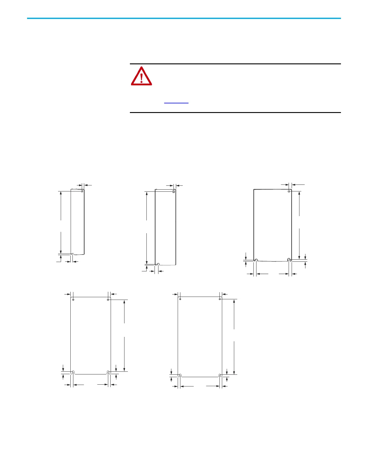
Drill-hole Patterns
The following views provide mounting-hole dimensions for the Kinetix 5100
servo drives.
Figure 16 - Mounting-hole Dimensions
ATTENTION: This drive contains electrostatic discharge (ESD) sensitive
parts and assemblies. You are required to follow static control precautions
when you install, test, service, or repair this assembly. If you do not follow
ESD control procedures, components can be damaged. If you are not
familiar with static control procedures, see Allen-Bradley publication
8000-4.5.2
, Guarding Against Electrostatic Damage or any other applicable
ESD Protection Handbook.
7.0
(0.28)
170
(6.67)
81.0
(3.19)
7.0
(0.12)
5.0
(0.20)
3.0
(0.12)
7.0
(0.12)
5.5
(0.22)
2.0
(0.08)
8.2
(0.32)
173
(6.79)
5.5
(0.22)
2.0
(0.08)
162
(6.40)
5.5
(0.22)
257
(10.12)
104
(4.09)
8.0
(0.31)
8.0
(0.31 )
8.0
(0.31 )
244.3
(9.62)
8.0
(0.31)
8.0
(0.31 )
8.0
(0.31 )
8.0
(0.31)
8.0
(0.31)
8.0
(0.31)
94.5
(3.72)
8.0
(0.31)
8.0
(0.31)
8.0
(0.31)
2198-E1004-ERS
Kinetix 5100 Drive
2198-E1007-ERS
and 2198-E1015-ERS
Kinetix 5100 Drives
2198-E2055-ERS
2198-E4055-ERS
Kinetix 5100 Drive
2198-E4020-ERS
2198-E4030-ERS
Kinetix 5100 Drive
2198-E1020-ERS
2198-E2030-ERS, 2198-E4004-ERS,
2198-E4007-ERS, and 2198-E4015-ERS
Kinetix 5100 Drives
Dimensions are in mm (in.)

 Loading...


