Rockwell Automation Publication 2198-UM004D-EN-P - December 2022 75
Chapter 3 Connector Data and Feature Descriptions
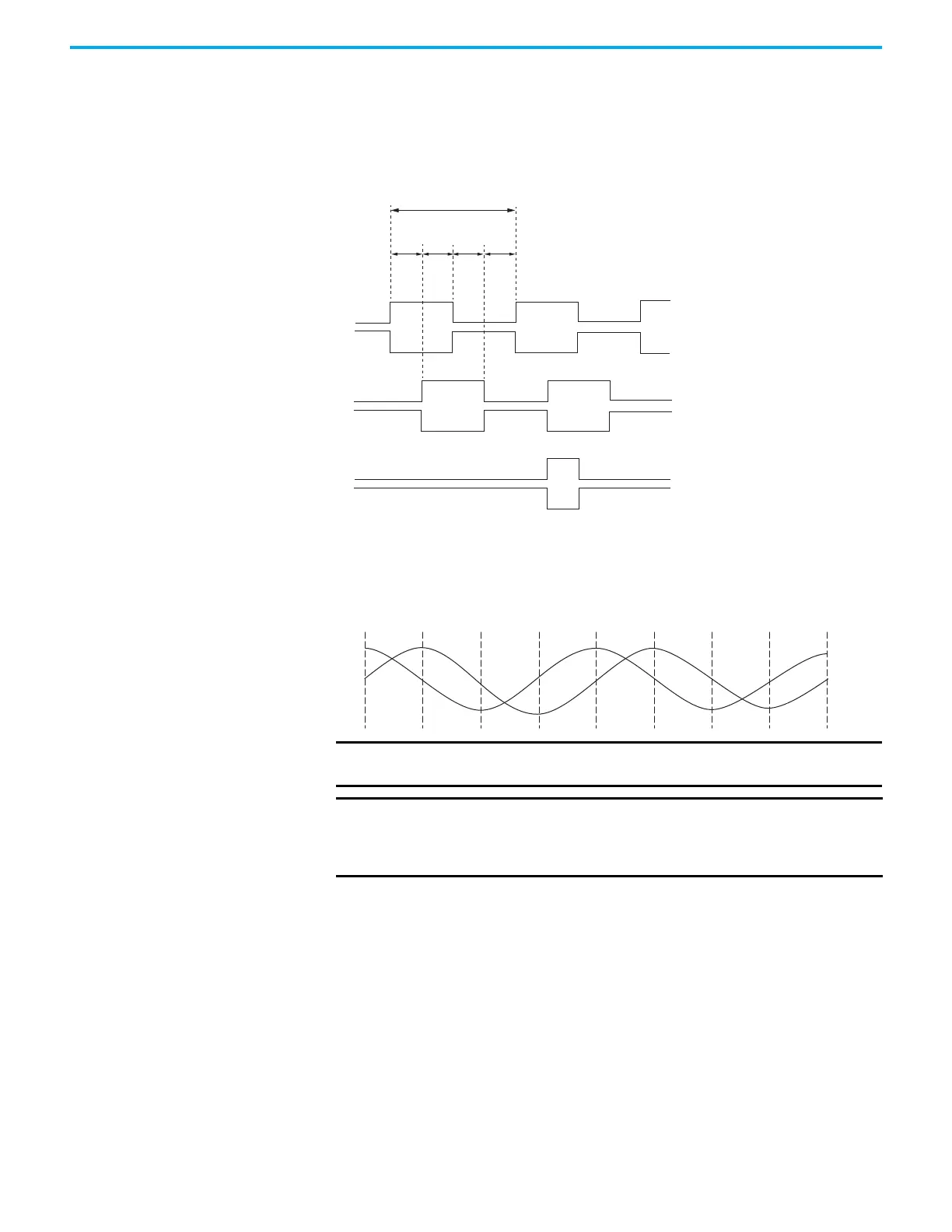
Encoder Phasing Definitions
For TTL encoders, the drive position increases when A leads B. Clockwise
motor rotation is assumed, when looking at the motor shaft.
Figure 41 - TTL Encoder Phasing
For Sin/Cos encoders, Hiperface for example, the drive position increases
when Cosine (B) leads Sine (A). Clockwise motor rotation is assumed, when
looking at the motor shaft.
Figure 42 - Sine/Cosine Encoder Phasing
The drive MFB connector uses Hall signals to initialize the commutation angle
for permanent magnet motor commutation.
A
/A
90°
90°
90° 90°
360°
B
/B
Z
/Z
IMPORTANT
The Sine/Cosine encoder signal phasing is different than the TTL
encoder signal phasing.
IMPORTANT
When using absolute feedback devices (for example, Hiperface) the
drive simulates a marker signal because these devices don't have a
marker signal required for the home-to-marker sequence to
complete.

 Loading...


