Rockwell Automation Publication 2198-UM004D-EN-P - December 2022 53
Chapter 3 Connector Data and Feature Descriptions
Power Connector Pinouts
Catalog numbers 2198-E1004-ERS, 2198-E1007-ERS, and 2198-E1015-ERS have
connector plugs on the top and bottom of the drive for power connections.
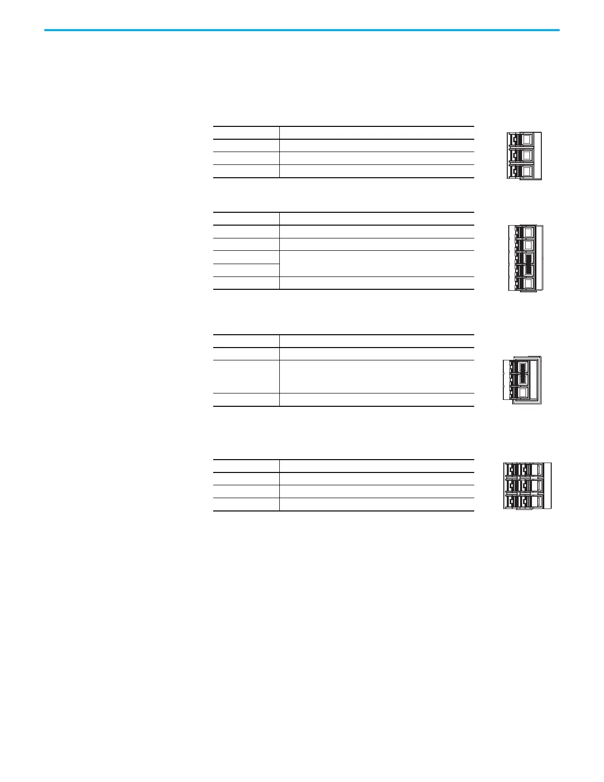
Table 15 - AC Input Power Connector Pinouts
Signal Description
L1 AC power in - L1 phase
L2 AC power in - L2 phase
L3 AC power in - L3 phase
Table 16 - Control AC Input Power Connector Pinout
Signal Description
L1C Control AC power in - L1C phase
L2C Control AC power in - L2C phase
P1
Reserved (not used)
(1)
(1) P1 and P2 jumper is applied (default) at the factory. Do not remove jumper.
P2
DC– Negative DC bus
Table 17 - Shunt Resistor Connector Pinout
Signal Description
DC+ Positive DC bus
ISH
Internal shunt connection
(1)
(applies to only 2198-E1004-ERS, 2198-E1007-ERS,
and 2198-E1015-ERS drives)
(1) For internal shunt, keep jumper applied between DC+ and ISH (default). Remove jumper and
connect external shunt between DC+ and ESH.
ESH External shunt connection (applies to all drives)
Table 18 - Motor-Power Connector Pinout
Signal Description
U Motor power out - U phase
V Motor power out - V phase
W Motor power out - W phase
L1 L2 L3
ESH
DC+
ISH
U V W

 Loading...


