54 Rockwell Automation Publication 2198-UM004D-EN-P - December 2022
Chapter 3 Connector Data and Feature Descriptions
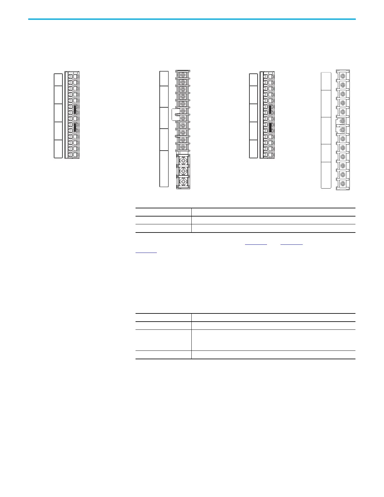
Catalog numbers 2198-E1020-ERS, 2198-E2030-ERS, 2198-E2055-ERS,
2198-E2075-ERS, 2198-E2150-ERS, and 2198-E4xxx-ERS have power
connections on the I/O terminal block on the front of the drive.
Figure 22 - Power Pinouts on I/O Terminal Block
For connector pinout descriptions, see Table 13 and Table 14 beginning on
page 50
.
The 2198-E2055-ERS, 2198-E2075-ERS, and 2198-E2150-ERS, 2198-E4020-ERS,
2198-E4030-ERS, 2198-E4055-ERS, 2198-E4075-ERS, and 2198-E4150-ERS
drives do not include an internal shunt resistor. However, an external shunt
resistor can be connected to the DC+ and ESH terminals.
P1
P2
DC–
L1
L2
L3
L1C
L2C
DC+
ESH
U
V
W
U
V
W
DC+
ISH
ESH
P1
P2
DC–
L1
L2
L3
L1C
L2C
U
V
W
DC+
ESH
P1
P2
DC–
L1
L2
L3
24V+
24V–
U
V
W
DC+
ISH
ESH
P1
P2
DC–
L1
L2
L3
24V+
24V–
I/O Terminal Block for 2198-E2055-
ERS, 2198-E2075-ERS, and 2198-
E2150-ERS, Servo Drives
I/O Terminal Block for
2198-E1020-ERS, and 2198-E2030-ERS
Servo Drives
I/O Terminal Block for
2198-E4004-ERS,
2198-E4007-ERS,
2198-E4015-ERS
Servo Drives
(a)
I/O Terminal Block for
2198-E4020-ERS,
2198-E4030-ERS,
2198-E4055-ERS,
2198-E4075-ERS, and
2198-E4150-ERS
Servo Drives
(a)
(a) P1 and P2 jumper is applied
(default) at the factory. Do not
Table 19 - Control Input Power Connector Pinout - (400V-Class Drives)
Signal Description
24V+ Control 24V+ DC
24V- Control 24V- DC common
Table 20 - Shunt Resistor Connector Pinout
Signal Description
DC+ Positive DC bus
ISH
Internal shunt connection
(1)
(applies to only 2198-E1020-ERS, 2198-E2030-ERS, 2198-E4004-ERS, 2198-E4007-ERS,
and 2198-E4015-ERS drives)
(1) For internal shunt, keep jumper applied between DC+ and ISH (default). Remove jumper and connect external shunt between
DC+ and ESH.
ESH External shunt connection (applies to all drives)

 Loading...


