Rockwell Automation Publication 2198-UM004D-EN-P - December 2022 55
Chapter 3 Connector Data and Feature Descriptions
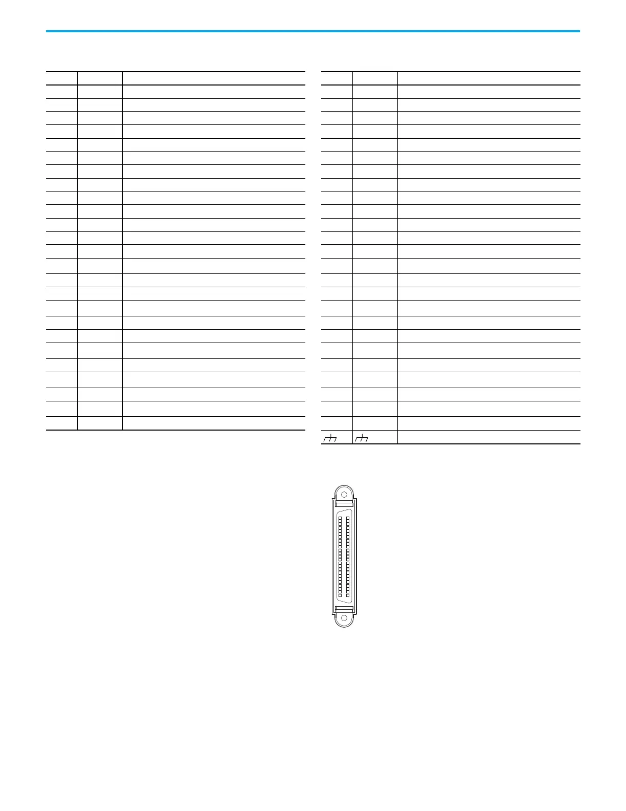
Figure 23 - Pin Orientation for 50-pin SCSI I/O Connector
Table 21 - I/O Connector Pinout
I/O Pin Signal Description I/O Pin Signal Description
1 OUTPUT4+ Digital output 4+ 26 OUTPUT4– Digital output 4–
2 OUTPUT3– Digital output 3– 27 OUTPUT5– Digital output 5–
3 OUTPUT3+ Digital output 3+ 28 OUTPUT5+ Digital output 5+
4 OUTPUT2– Digital output 2– 29 INPUT9 Digital input 9 (high speed)
5 OUTPUT2+ Digital output 2+ 30 INPUT8 Digital input 8
6 OUTPUT1– Digital output 1– 31 INPUT7 Digital input 7
7 OUTPUT1+ Digital output1+ 32 INPUT6 Digital input 6
8 INPUT4 Digital input 4 33 INPUT5 Digital input 5
9 INPUT1 Digital input 1 34 INPUT3 Digital input 3
10 INPUT2 Digital input 2 35 BPWR External power input of BX+/BX– for single-end operation
11 DCOM Common for digital inputs, connected to +24 or 0V DC 36 BX+ Pulse input B+/DIR+/CCW+
12 AGND Analog input signal ground 37 BX– Pulse input B–/DIR–/CCW–
13 AGND Analog input signal ground 38 INPUT10 Digital input 10 (high speed)
14 —
Reserved
(1)
39 APWR External power input of AX+/AX– for single-end operation
15 AOUT2 Analog monitor output 2 40 OUTPUT6– Digital output 6–
16 AOUT1 Analog monitor output 1 41 AX– Pulse input A–/Step–/CW–
17 —
Reserved
(1)
42 COMMAND2 Analog position or speed command input
18 COMMAND1 Analog torque input 43 AX+ Pulse input A+/Step+/CW+
19 AGND Analog input signal ground 44 AGND Analog input signal ground
20 —
Reserved
(1)
45 —
Reserved
(1)
21 AMOUT+ Buffered encoder output Ch A+ 46 OUTPUT6+ Digital output 6+
22 AMOUT– Buffered encoder output Ch A– 47 —
Reserved
(1)
23 BMOUT– Buffered encoder output Ch B– 48 OCZMOUT Buffered Encoder Output Ch Z open collector
24 ZMOUT– Buffered encoder output Ch Z– 49 —
Reserved
(1)
25 BMOUT+ Buffered encoder output Ch B+ 50 ZMOUT+ Buffered encoder output Ch Z+
Drain wire
(1) The reserved pins are not present on the 2198-TBIO terminal expansion block.

 Loading...


