64 Rockwell Automation Publication 2198-UM004D-EN-P - December 2022
Chapter 3 Connector Data and Feature Descriptions
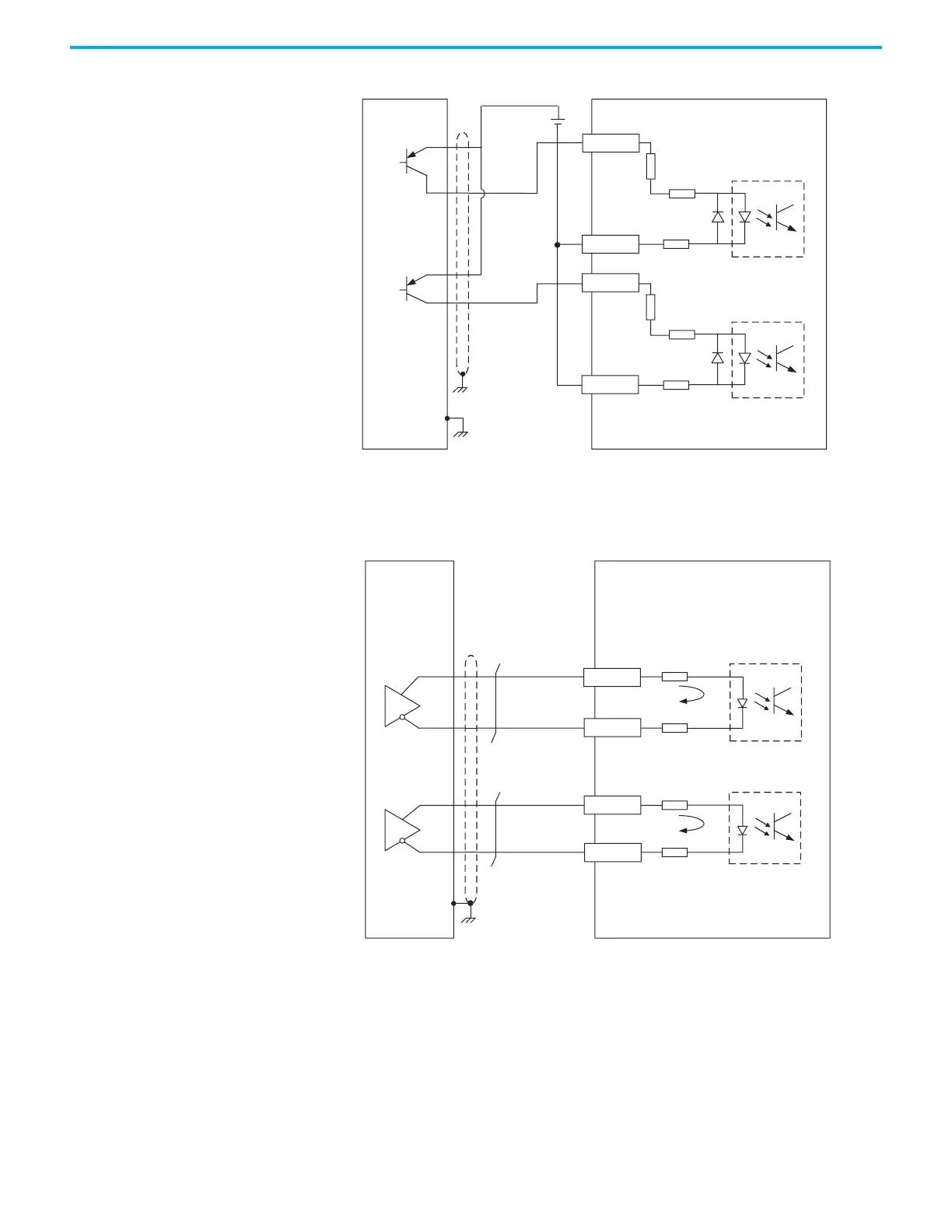
Figure 33 - Pulse Input - Single-ended Configuration (current sinking)
In Differential mode, the p
ulse input (line driver) only accepts 2.8…3.6V DC
(5V DC nominal). Do not apply 24V power.
Figure 34 - Pulse Input (line driver) Configuration
51 Ω
51Ω
51Ω
51Ω
24V DC
+
-
.
5
kΩ
1.5kΩ
Pulse input frequency (max):
200 kHz
Pulse input frequency (max):
200 kHz
39
41
BPWR
35
37
Pulse
B–
APWR
Pulse A–
Servo Drive
Controller
I/O Connector with
2198-TBIO Expansion Block
51Ω
51Ω
51Ω
51Ω
/S IG N
/P U LS E
SIGN 36
37
43
PULSE
41
Pulse i nput frequency (max):
4 MHz
Pulse i nput frequency (max):
4 MHz
Pulse B+
Pulse B–
Pulse A+
Pulse A–
Servo Drive
Controller
I/O Connector with
2198-TBIO Expansion Block

 Loading...


