Rockwell Automation Publication 2198-UM004D-EN-P - December 2022 469
Appendix A Interconnect Diagrams
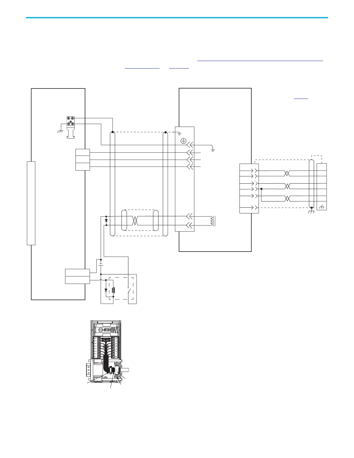
The 2090-DANFCT-Sxx feedback cable is equipped with a drive-end connector
that is not compatible with the 15-pin (MFB) feedback connector. To provide
battery backup to the encoder, you can remove the drive-end connector and
prepare the cable shield and conductors for wiring to the 2198-K51CK-D15M
feedback connector kit. See Cable Preparation for Kinetix TL and TLY Motor
Power Cables on page 98 for more information.
Figure 249 - Kinetix 5100 with Kinetix TL Rotary Motors
1
2
W
V
U
GND
W
V
U
Blue
Black
Brown
White
Black
Shield
Green/Yellow
1
2
3
4
5
6
7
8
9
10
11
12
13
14
15
5
3
2
1
BR–
BR+
40
46
OUTPUTx–
OUTPUTx+
GRAY
WHT/GRAY
7
8
14
6
9
ORANGE
WHT/ORANGE
14
BAT+
BAT-
+5VDC
ECOM
SHIELD
BAT+
BAT-
SD+
SD-
BROWN
WHT/BROWN
12
13
5
10
Motor Brake
Motor Power
Connector
TL-Axxxx-B (230V)
Servo Motors with
High-resolution Feedback
Motor Feedback
(MFB) Connector
Three-phase
Motor Power
Motor
Feedback
Refer to connector kit
illustration (lower left)
Refer to table on page 457
for
note information.
2090-DANFCT-Sxx (standard)
Flying-lead Feedback Cable
(with drive-end connector removed)
2090-DANPT-16Sxx
Motor Power Cable
Note 13
Cable Shield
Clamp
2198-K51CK-D15M
Feedback Connector Kit
2090-DANBT-18Sxx
Motor Brake Cable
Note 13
2198-Exxxx-ERS
Kinetix 5100 Drives
Note 11
2198-K51CK-D15M
Feedback Connector Kit
Ground Technique for
Feedback Cable Shield
360° exposed shield that is secured
under clamp.
Clamp Screws (2)
Clamp
Tie Wrap
Note 7
Note 9
Customer
Supplied
24V DC
Relay
I/O Connector with
2198-TBIO Expansion Block

 Loading...


