EasyManuals Logo

Rockwell Automation Allen-Bradley Kinetix 5100 User Manual

Rockwell Automation Allen-Bradley Kinetix 5100
556 pages
To Next Page IconTo Next Page
To Previous Page IconTo Previous Page
Page #474 background imageLoading...
Page #474 background image
474 Rockwell Automation Publication 2198-UM004D-EN-P - December 2022
Appendix A Interconnect Diagrams
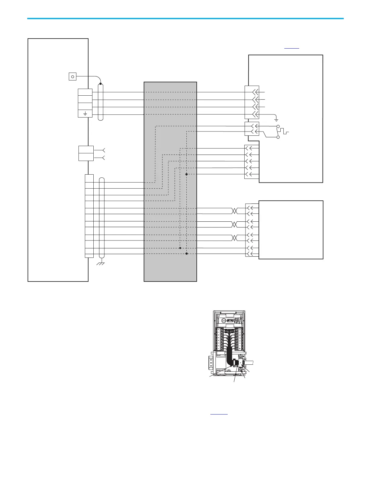
Figure 254 - Kinetix 5700 Drives with Kinetix LDC Linear Motors (flying-lead cables)
GND
4
3
2
1
RED
WHITE
BLACK
GREEN/YELLOW
BLACK
BLACK
RED
WHITE
BLUE
ORANGE
BLACK
TS+
TS-
POWER
S1
S2
S3
COM
SIN+
SIN-
COS+
COS-
IM+
IM-
POWER
COM
TS+
S1
S2
S3
13
8
12
11
(AM+)
(AM-)
(BM+)
(BM-)
1
2
3
4
5
10
14
6
SIN+
SIN-
COS+
COS-
IM+
IM-
POWER
COM
(AM+)
(AM-)
(BM+)
(BM-)
U
V
W
D+
D-
1
2
U
V
W
U
V
W
LDC-Cxxxxxx-xHTx0
Linear Motor Coil with
Sin/Cos or TTL External Encoder
and Flying-lead Cables
Three-phase
Motor Power
Motor Feedback
(MF) Connector
Thermostat
Refer to table on page 457
for note
External
Sin/Cos or (TTL)
Encoder
Hall Effect
Module
Wire as shown using
cable type appropriate for
your application.
Motor Power
(MP) Connector
Cable Shield
Clamp
Note 11
2198-Exxx -ERSx
Kinetix 5100 Servo Drives
Feedback
Connector
Grounding Techniques for Feedback Cable Shield
2198-K51CK-D15M
Feedback Connector Kit
360° exposed shield that is secured
under clamp.
Clamp Screws (2)
Clamp
Tie Wrap
See the Kinetix 5100 Feedback Connector Kit
Installation Instructions,
publication 2198-IN019
, for connector kit
specifications.

Table of Contents

Other manuals for Rockwell Automation Allen-Bradley Kinetix 5100

Questions and Answers:

Question and Answer IconNeed help?

Do you have a question about the Rockwell Automation Allen-Bradley Kinetix 5100 and is the answer not in the manual?

Rockwell Automation Allen-Bradley Kinetix 5100 Specifications

General IconGeneral
BrandRockwell Automation
ModelAllen-Bradley Kinetix 5100
CategoryServo Drives
LanguageEnglish

Related product manuals