104 Rockwell Automation Publication 2198-UM004D-EN-P - December 2022
Chapter 4 Connect the Kinetix 5100 Drive System
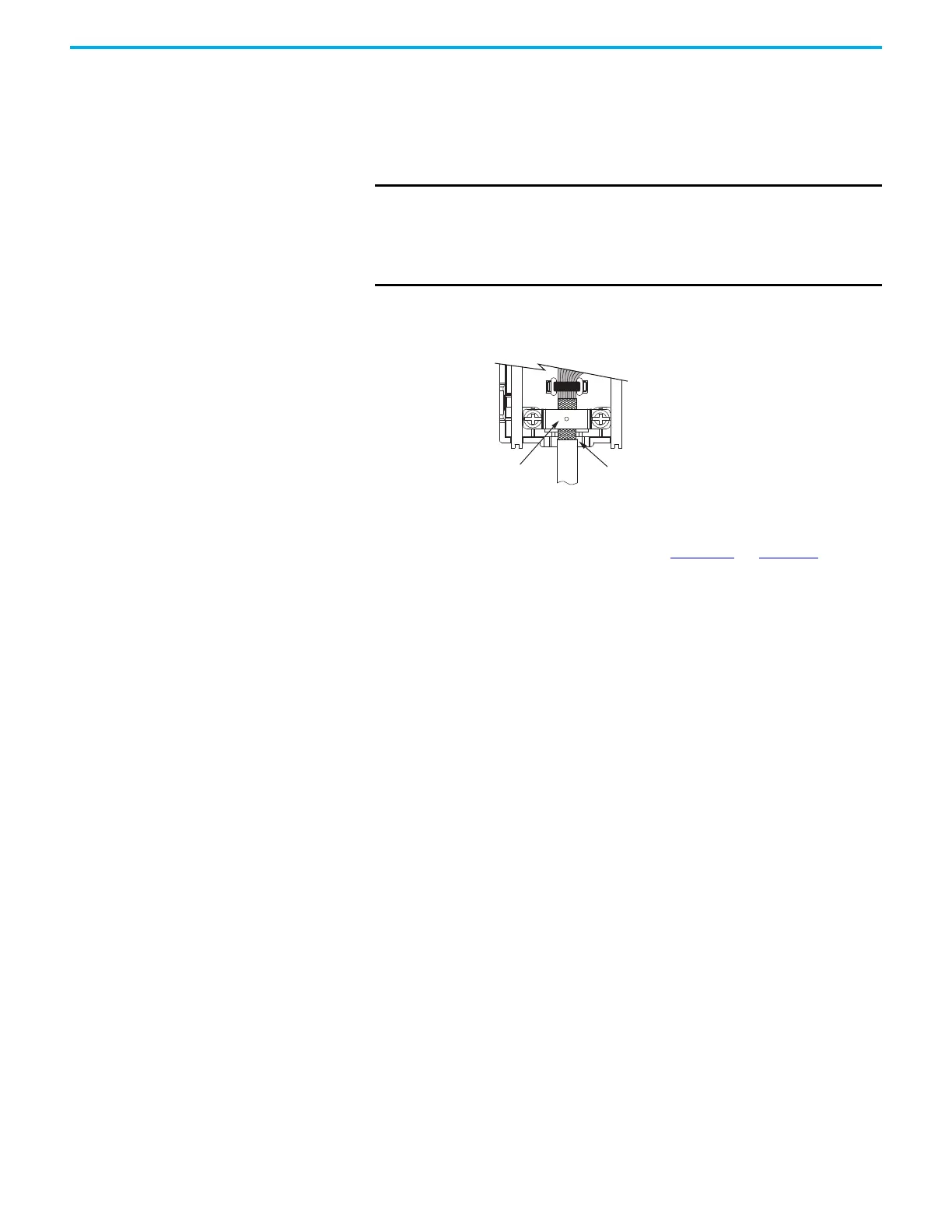
Apply the Connector Kit Shield Clamp
Follow these steps to apply the connector kit shield clamp.
1. Position the 12 mm (0.5 in.) of exposed cable shield over the ground pad
to achieve a high-frequency bond.
2. Place the shield clamp over the cable shield and install the clamp screws.
Apply 0.34 N•m (3.0 lb•in) torque to each screw.
3. Route and insert each wire to its assigned terminal, apply 0.20 N•m
(1.8 lb•in) maximum torque to each screw.
Refer to the connector pinout as shown in Figure 67
on page 107.
4. Attach the tie-wrap (customer-supplied) through the slots and around
the cable shield for stress relief and to create a high-frequency bond
between shield and ground pad.
IMPORTANT
Cable preparation and positioning that provides a high-
frequency bond between the shield braid and clamp is
required to optimize system performance.
Also, make sure that the cable is positioned where the cover
clamps onto the jacket for added stress relief.
Shield Clamp
Cable positioned where the cover
clamps onto the cable jacket.

 Loading...


