Rockwell Automation Publication 2198-UM004D-EN-P - December 2022 107
Chapter 4 Connect the Kinetix 5100 Drive System
Table 66 - 2090-DANFCT-Sxx Feedback Cables
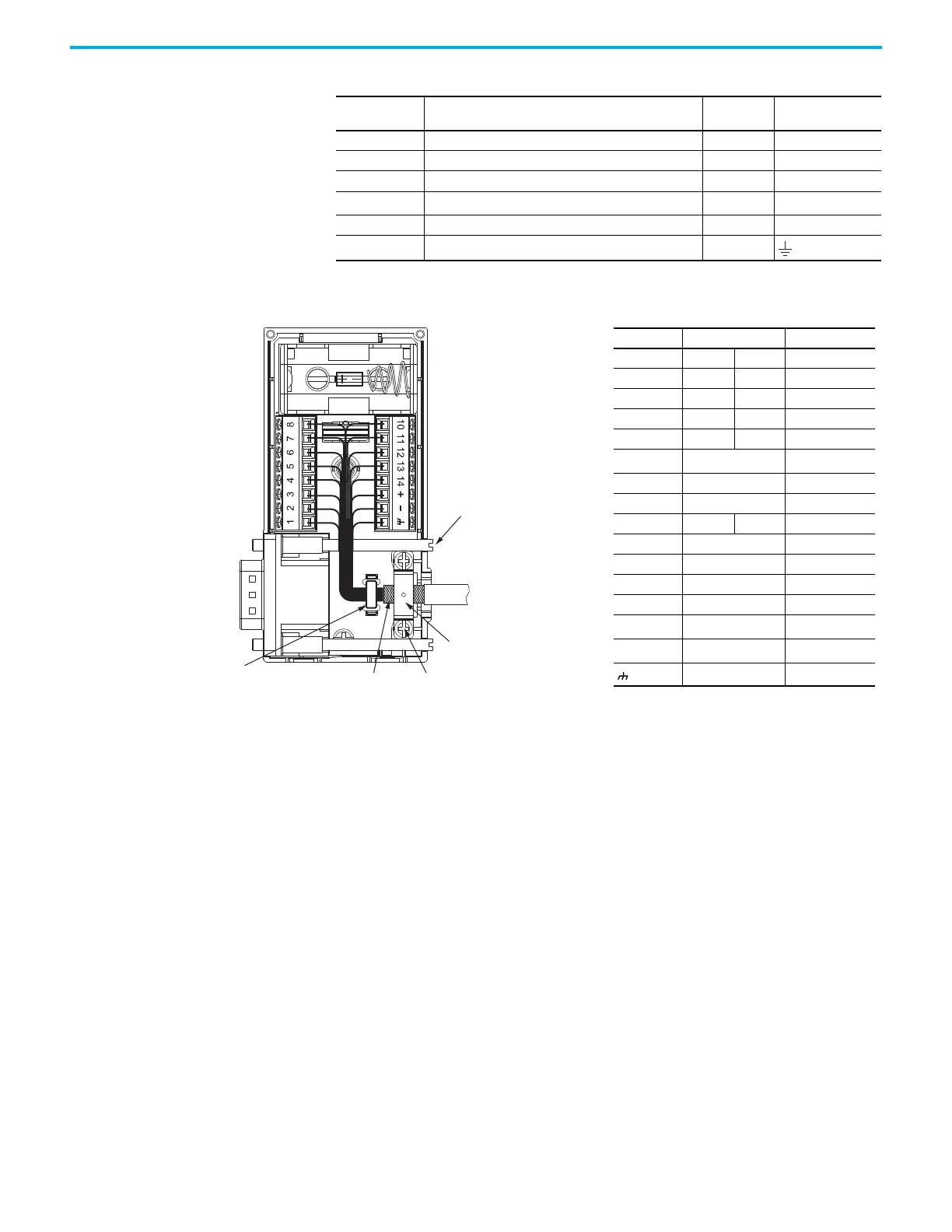
Figure 67 - Wire the 2198-K51CK-D15M Feedback Connector Kit
Motor Pin
TL-Axxxx-B
17-bit Absolute, Multi-turn, High-resolution Feedback
Wire Color
2198-K51CK-D15M
Connector Kit Pin
12 SD+ Brown 5
13 SD– White/Brown 10
7EPWR_5V Gray14
8 ECOM and BAT- White/Gray
6
(1)
(1) BAT- is tied to ECOM (pin 8) in the cable.
14 BAT+ Orange BAT+
9Drain –
Shield Clamp
Clamp Screws (2)
Tie Wrap is
recommended for
Stress Relief and
Wire Management
Exposed Shield Aligned
Under the Shield Clamp
8-pin
Connector (2x)
15-pin D-sub to
Motor Feedback (MFB)
Connector
Kinetix 2090
Feedback Cable
Mounting
Screws (2x)
1. Place exposed cable shield
in the channel.
2. Place the shield clamp over
the exposed shield.
3. Tighten screws, torque
0.35 N•m (3.097 lb•in).
Terminal Signal Wire Color
1 SIN+ AM+ Black
2 SIN– AM– White/Black
3 COS+ BM+ Red
4 COS– BM– White/Red
5 DATA+ IM+ Green
6
ECOM
(1)
(1) The ECOM and TS- connections are tied together and
connect to the cable shield.
White/Gray
7 EPWR_9V Orange
8 S3 White/Yellow
10 DATA– IM– White/Green
11 TS+ White/Orange
12 S1 White/Blue
13 S2 Yellow
14 EPWR_5V Gray
+ Battery +
N/A
(2)
(2) See cable pinouts for wire colors.
– Battery –
N/A
(2)
Drain Shield

 Loading...


