238 Rockwell Automation Publication 2198-UM004D-EN-P - December 2022
Chapter 10 Modes of Operation
•Z: Logic Type
Digital circuits use 0 and 1 to represent the voltage level of low and high
respectively. Using positive logic, 1 represents high voltage and 0 represents
low voltage; using negative logic, 1 represents low voltage and 0 represents
high voltage.
For example:
MHz
kHz
kHz
MHz
Positive logic
Negative logic
Logic
type
Logic
type
Pulse
type
Pulse
type
Pulse input
Pulse phase lead
Pulse phase lag
Forward
Reverse
Pulse input
Reverse
Forward
Sign = low
Sign = high
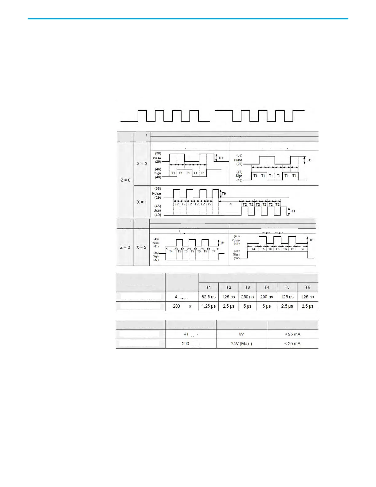
Pulse Specification
Min. Allowed Time Width
Max. Input
Frequency
Max. Input Frequency
Pulse Specification
Differential signal
Differential signal
Open-collector
Open-collector
Voltage Forward current

 Loading...


