376 Rockwell Automation Publication 2198-UM004D-EN-P - December 2022
Chapter 12 Motion Control Applications
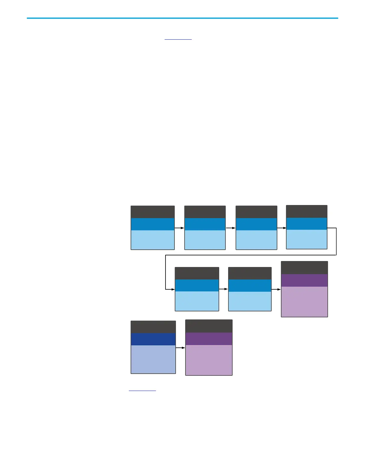
The following example describes how the PR command works and is
illustrated in Figure 184
.
1. PR#1 confirms that the Capture function is disabled, with ID331.X
(P5.039.X) NAME Bit 0 = 0. This confirmation is done in case the previous
Capture did not complete.
2. PR#2 sets the start address of data array ID 328 (P5.036) to #100.
3. PR#3 sets the CAPTURE remained count ID 330 (P5.038) as 3, which
executes 3 captures before the capturing function is completed.
4. PR#4 sets the First Capture Reset Position (ID368, P5.076) to 0 for the
first capture point.
5. PR#5 sets a cyclic capture mode and uses a 1 ms delay before executing
the next PR command.
6. PR#6 enables the capture function and resets the first point. Once the
data capture is complete, the drive executes PR#50. It selects the main
encoder of the motor as the Axis Source and applies 'normally closed'
contact as trigger logic with trigger interval of 2 ms.
7. PR#7 sets the initial speed command at 50 rpm.
8. Once the last capture occurs, PR#50 executes a Point-to-Point move
(proceed to next), with CMD type CAP (type 11) and
Position CMD Data = 50000 PUU
9. PR#51 uses a PR with command type of Constant speed control.
Figure 184 - PR Command with Application of High-speed Capture (DI9 example)
Figure 185 shows how the data is captured in the data array when the capture
function is executed. At (1) after DI9 is triggered, the capturing axis is reset to 0
and the data is stored in data array #100. When DI9 is triggered the second (2)
and third (3) times, the position data is written to the data arrays #101 and
#102, respectively. Once the first capture cycle is completed, the DO:CAP_OK
[0x16] signal turns on and then PR#50 (high speed position capture command)
and PR#51 (motion with fixed speed) are executed. The servo drive will execute
PR#1 (I)
Write
DLY=[0] 0 ms
P5.039=0x2030
PR#3 (I)
Write
DLY=[0] 0 ms
P5.038=3
PR#4 (I)
Write
DLY=[0] 0 ms
P5.076=0
PR#2 (I)
Write
DLY=[0] 0 ms
P5.036=100
PR#50 (I)
Position
DLY=[0] 0 ms
50000 PUU
CAP
100rpm
PR#7 (I)
Speed
DLY=[0] 0 ms
50 rpm
Acc=[0] 3.33 ms
Dec=[0] 3.33 ms
PR#6 (I)
Write
DLY=[0] 0 ms
P5.039=0x203B
PR#5 (I)
Write
DLY=[10] 1 ms
P1.019=0x0001
PR#51
Speed
DLY=[0] 0 ms
50 rpm
Acc=[0] 3.33 ms
Dec=[0] 3.33 ms

 Loading...


