Rockwell Automation Publication 2198-UM004D-EN-P - December 2022 385
Chapter 12 Motion Control Applications
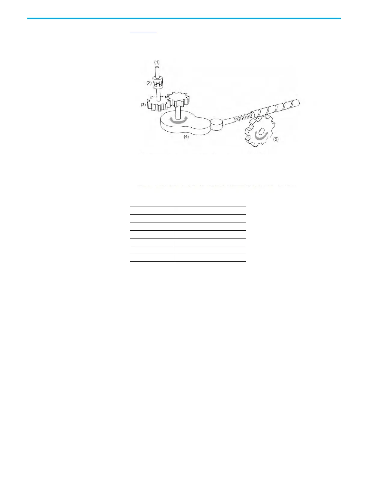
Figure 193 uses the mechanical cam concept to illustrate the E-CAM parameter
settings.
Figure 193 - Electronic cam simulates mechanical cam assembly with servo drive parameters
(1) Master Axis: master axis signal source is set by ID376 (P5.088.Y)
(2) Clutch: time to engage or disengage is set by ID376 (P5.088.UZ), ID375 (P5.087), ID377 (P5.089)
(3) Master Axis Gear Ratio: pulse input resolution is set by ID371 (P5.083), ID372 (P5.084)
(4) E-CAM Curve: curve is set by ID369 (P5.081), ID370 (P5.082), ID373 (P5.085), scale is set by ID311 (P5.019)
(5) Slave Axis Gear Ratio: output signal resolution is set by ID151 (P1.044), ID152 (P1.045)
Table 121 - E-CAM General Settings
Parameter Name
ID245 (P2.073) ECamConfiguration
ID246 (P2.074) ECamDIDelayTimeCompensation
ID247 (P2.075) ECamAlignementTargetPosition
ID248 (P2.076) ECamControlConfiguration
ID249 (P2.078) ECAMDOCamArea_RisingEdge
ID250 (P2.079) ECAMDOCamArea_FallingEdge

 Loading...


