406 Rockwell Automation Publication 2198-UM004D-EN-P - December 2022
Chapter 12 Motion Control Applications
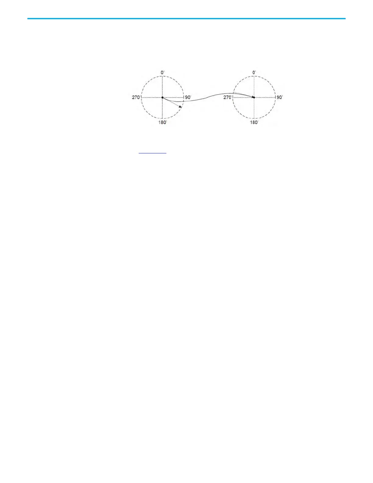
• Cubic curve — Both the starting angle and the ending angle can be
adjusted. The change of the angle will affect the speed change when
leaving the starting point and entering the target point. Improper angle
setting causes the speed to change sharply.
Figure 215 - Starting and Ending Angle
The KNX5100C software E-CAM table creation by cubic curve method is shown
in Figure 216
. The following is the operation steps of the cubic curve table
creation:
1. Set E-CAM curve.
The cubic curve table data includes angle, slave axis position, curve type,
starting angle and ending angle. You can change the data corresponding
to each point by dragging the turning point in the Cubic Curve
Simulation diagram, and can also insert or delete a specific turning
point. When dragging, inserting, or deleting a turning point, the data
content in the Cubic Data changes accordingly. However, when directly
inputting the desired content into Cubic Data, click Create Cubic Curve
to see the cubic curve simulation.
2. After completing the setting of the turning point, set the sample angle
(Sample ang.) and click Convert to E-CAM table.
The software automatically fills the data of each sampling point into the
E-CAM table according to the curve. The more points, the more precise
the E-CAM curve. If the position of the slave axis is too small, that can
cause the speed jitter. You can adjust the parameter instance ID311
(P5.019) ECamCurveScale to enlarge the value in the table to improve the
speed jitter.
3. After confirming that the curve is correct, click Download Table.
The E-CAM curve is written to the data array. If you have selected ‘Burn
to EEPROM when download’, when you click the download button, the
data array is written to the EEPROM that can be held after the power is
turned off.

 Loading...


