Rockwell Automation Publication 2198-UM004D-EN-P - December 2022 419
Chapter 13 Kinetix 5100 Safe Torque Off (STO) Feature
Figure 228 - Single-axis Relay Configuration (Stop Category 0)
(1) Bypass Jumper is removed from SB+ and SB-.
Sinking output status is true (=1) when the drive displays E 500 status (SS+ and SS- are closed).
In this example, the drive is shown with two axes configuration in a relay
configuration for Stop Category 0 per IEC-60204-1 Safety of Machinery
Directive.
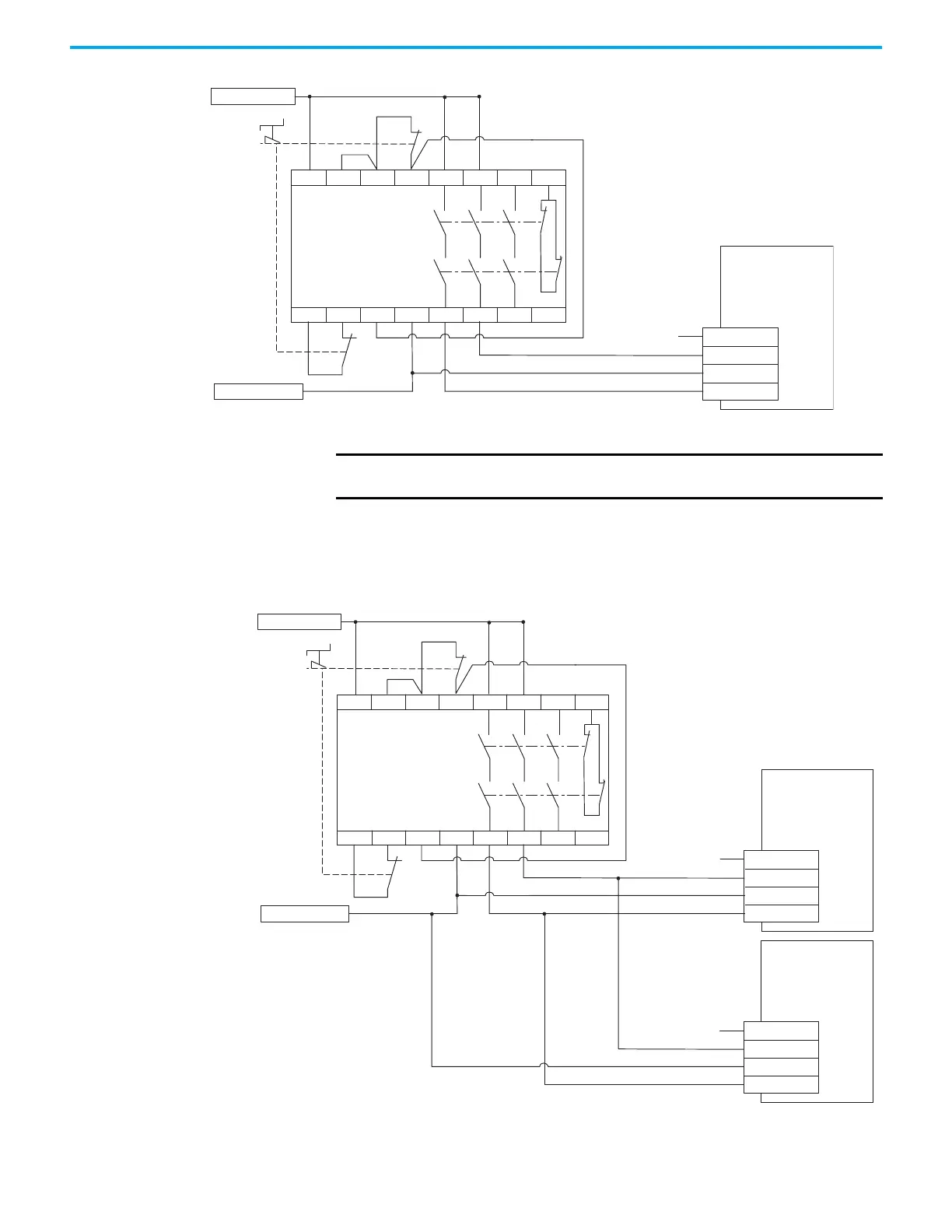
Figure 229 - Multiple-axis Relay Configuration (Stop Category 0)
(1) Bypass Jumper is removed from SB+ and SB-.
Sinking output status is true (=1) when the drive displays E 500 status (SS+ and SS- are closed)
SS+/SS–
S1
S1C/S2C
S2
S21 S22 S34 A2 14 24 34 42
A1 S11 S52 S12 13 23 33 41
Kinetix 5100 Drive
STO
(1)
Connector with
Wiring Header
External 24V COM
STO Demand
External +24V DC
Allen-Bradley
Monitoring Safety Relay
MSR127RP (440R-N23135)
IMPORTANT
Reset of the STO fault is required via digital input DI.ARST or
raC_xxx_5100_MAFR instruction.
SS+/SS–
S1
S1C/S2C
S2
S21 S22 S34 A2 14 24 34 42
A1 S11 S52 S12 13 23 33 41
SS+/SS–
S1
S1C/S2C
S2
Kinetix 5100 Drive
STO
(1)
Connector with
Wiring Header
External 24V COM
STO Demand
External +24V DC
Allen-Bradley
Monitoring Safety Relay
MSR127RP (440R-N23135)
Kinetix 5100 Drive
STO
(1)
Connector with
Wiring Header

 Loading...


