58 Rockwell Automation Publication 2198-UM004D-EN-P - December 2022
Chapter 3 Connector Data and Feature Descriptions
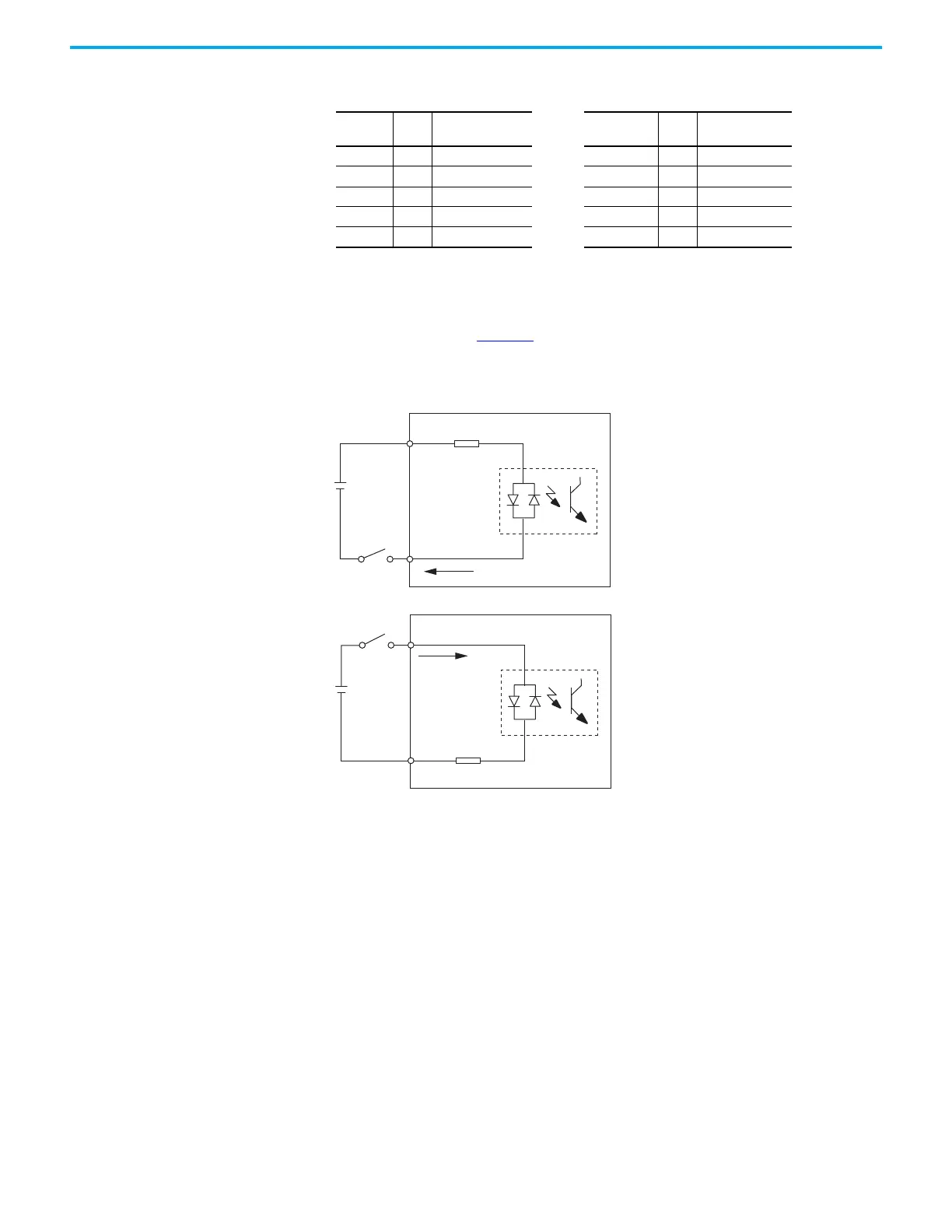
Wiring and Signal Specifications
The digital inputs are optically isolated and sink up to 24V DC. Electrical
details are shown in Table 25
. You can configure the inputs for PNP sourcing or
NPN sinking.
Figure 27 - Digital Input Circuitry
Table 24 - DigitaI Input Signal Parameters
Signal Pin
Configuration
Parameter
Signal Pin
Configuration
Parameter
INPUT1 9 ID195 (P2.010) INPUT6 32 ID200 (P2.015)
INPUT2 10 ID196 (P2.011) INPUT7 31 ID201 (P2.016)
INPUT3 34 ID197 (P2.012) INPUT8 30 ID202 (P2.017)
INPUT4 8 ID198 (P2.013) INPUT9 29 ID220 (P2.036)
INPUT5 33 ID199 (P2.014) INPUT10 38 ID221 (P2.037)
24V DC
INPUTx
DCOM
4.7 kΩ,
approx.
24V DC
INPUTx
DCOM
4.7 kΩ,
approx.
Servo Drive
Servo Drive
NPN Transistor (Source mode)
PNP Transistor (Sink mode)

 Loading...


