Rockwell Automation Publication 2198-UM004D-EN-P - December 2022 59
Chapter 3 Connector Data and Feature Descriptions
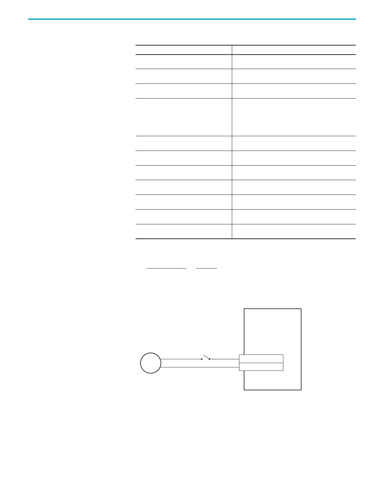
Digital Input Wiring
See Digital Inputs on page 57 for the default digital input assignments for
Kinetix 5100 drives.
In this example, Servo On is assigned to digital input 1 as a sinking type input.
Figure 28 - Digital Input Example
Table 25 - Digital Input Specifications
Attribute Value
Digital input response (delay)
• Standard inputs: 1.25 ms, max
• High speed inputs: 3 µs
Digital inputs scan time
• Standard inputs: 500 µs, max
• High speed inputs: 1 µs
Type Current sourcing and current sinking (IEC61131-2 Type 1)
Dedicated functions
• Standard inputs: INPUT1…INPUT8 and DCOM.
• High speed inputs (registration inputs): INPUT9, INPUT10, and
DCOM.
• When configured as Disabled, inputs can be used by
programs as a programming condition.
Only one function at a time is possible.
Input current (with 26.4V applied) 6 mA, max
ON state voltage 15…26.4V
OFF state voltage –1.0…5.0V
Pulse reject filtering (all digital inputs) 0.5 µs
Propagation delay (registration functions) 3 µs
Registration accuracy 3 µs
Registration repeatability 1 µs
24V DC
Supply
Servo On (INPUT1)
DCOM
+24V DC
–24V COM
9
11
2198-Exxxx-ERS
Kinetix 5100 Servo Drive
I/O Connector with
2198-TBIO Expansion Block

 Loading...


