62 Rockwell Automation Publication 2198-UM004D-EN-P - December 2022
Chapter 3 Connector Data and Feature Descriptions
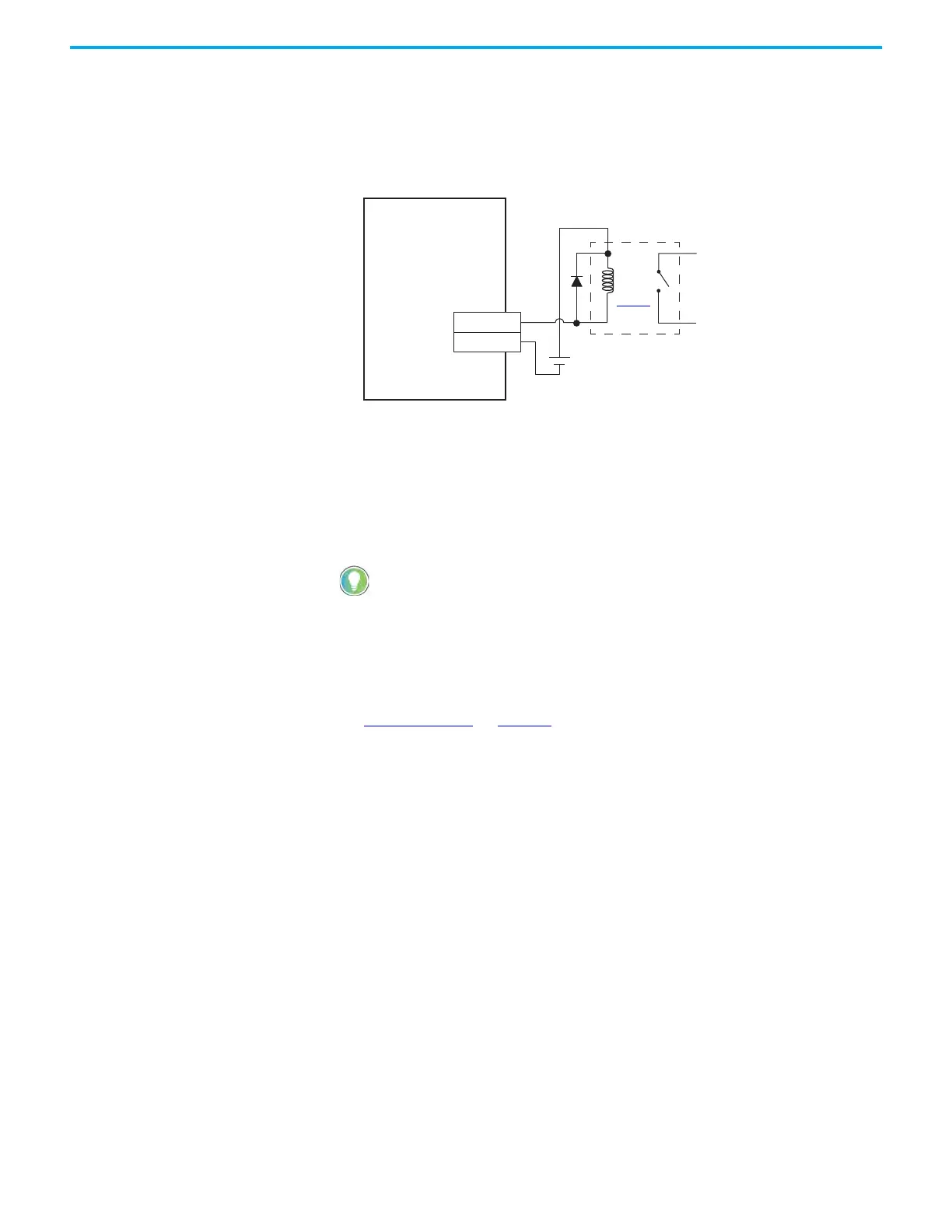
Digital Output Wiring
In this example, digital output 1 (pin 7+, pin 6–) is connected to an output relay
that changes a contact state used in a PLC or other circuit as shown.
Figure 30 - Digital Output Example
(1) Customer-supplied diode or MOV suppression device.
The I/O connector provides up to six digital outputs. Digital outputs are open-
collector type and are configurable with KNX5100C software.
An example brake circuit contains the following components:
• Digital output 40 mA (max) continuous current.
• Relay 700-HK36Z24 with DIN mount 700-HN121 or equivalent
• Choose from these suppression devices:
- 1N4004 diodes or equivalent
- Bulletin 199-MSMV1 MOV or equivalent
See Digital Outputs
on page 60 for the default digital output assignments for
Kinetix 5100 drives.
2198-Exxxx-ERS
Kinetix 5100 Servo Drive
I/O Connector with
2198-TBIO Expansion Block
Relay
(9)
page 45
To PLC or
Other Circuit
Customer Supplied
+24V DC
(1)
Choose a relay rated for 40 mA continuous current or less.

 Loading...


