Rockwell Automation Publication 2198-UM004D-EN-P - December 2022 61
Chapter 3 Connector Data and Feature Descriptions
Wiring and Signal Specifications
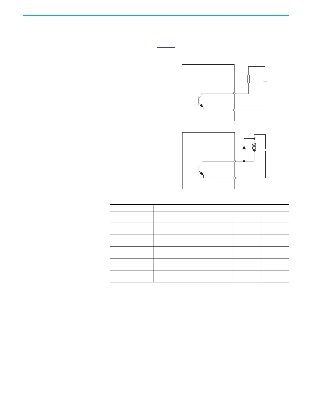
The digital outputs are optically isolated and sink up to 24V DC. Electrical
details are shown in Table 27
.
Figure 29 - Digital Output Circuitry
OUTPUTx–
OUTPUTx+
24V DC
R
OUTPUTx–
OUTPUTx+
24V DC
In this example, the drive applies the external
24V DC power supply to a resistive load.
In this example, the drive applies the external
24V DC power supply to an inductive load.
Servo Drive
Servo Drive
Table 27 - Digital Output Signal Specifications
Parameter Description Min Max
ON state current Current flow when the output transistor is ON – 40 mA
OFF state current Current flow when the output transistor is OFF – 0.1 mA
ON state voltage Voltage across the output transistor when ON – 1.5V @ 40 mA
OFF state voltage Voltage across the output transistor when OFF – 30V
Scan time
Interval of the digital outputs status updating in
drive firmware
–250 µs
Pass through delay
Signal propagation delay from the firmware-
accessible registers to the digital output
–1.0 ms

 Loading...


