90 Rockwell Automation Publication 2198-UM004D-EN-P - December 2022
Chapter 4 Connect the Kinetix 5100 Drive System
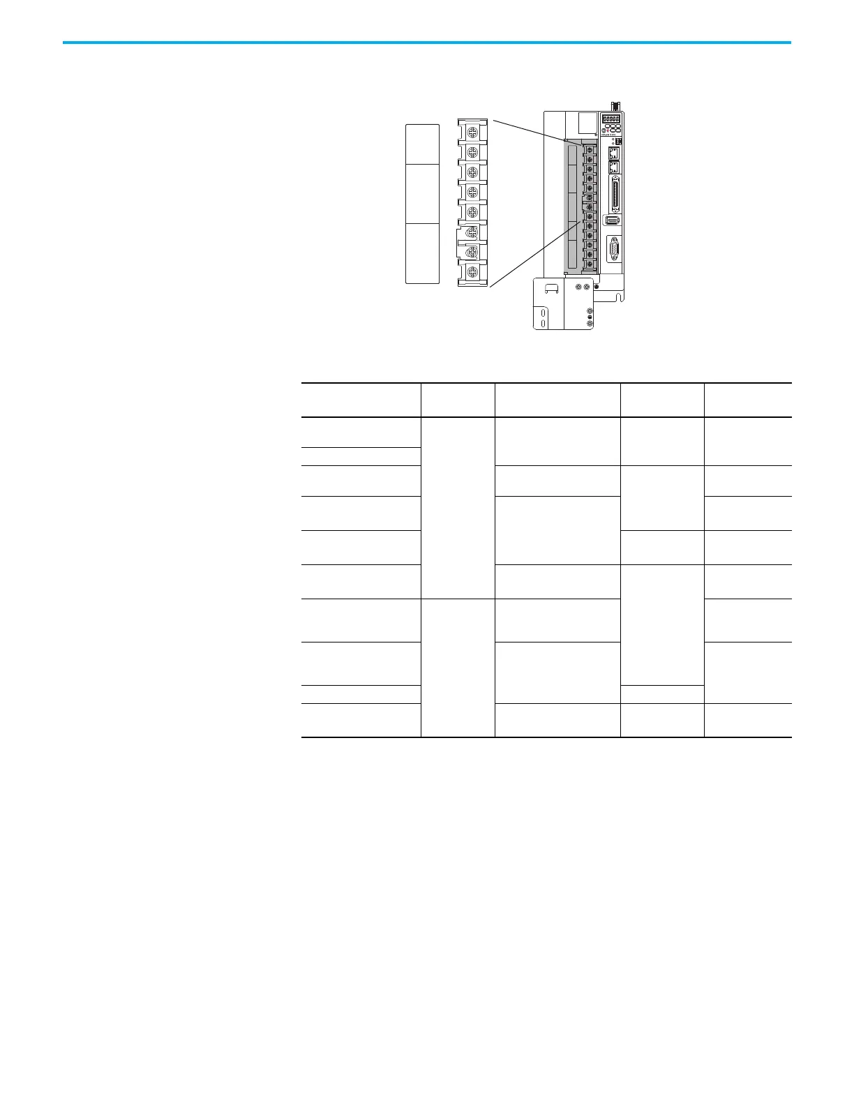
Figure 57 - 2198-E4020-ERS, 2198-E4030-ERS, 2198-E4055-ERS, 2198-E4075-ERS, and
2198-E4150-ERS Servo Drives
NET
MOD
CHARGE
I/O
AUX
U
V
W
DC+
ESH
P1
P2
DC–
L1
L2
L3
24V+
24V–
MFB
2
1
P1
P2
DC–
L1
L2
L3
24V+
24V–
Kinetix 5100 Servo Drives
(2198-E4020-ERS drive is shown)
Front View
Control Input Power
Connections
Mains Input Power
Connections
Reserved
(not used)
Table 47 - Input Power Connector Specifications
Kinetix 5100 Drive
Cat. No.
Connects to
Terminals
Recommended Wire Size
mm
2
(AWG)
Strip Length
mm (in.)
Torque Value
N•m (lb•in)
2198-E1004-ERS
2198-E1007-ERS
L1
L2
L3
L1C
L2C
P1
P2
DC-
0.20…3.31
(24…12)
11 (0.4)
N/A
(1)
(1) This connector uses spring tension to hold wires in place.
2198-E1015-ERS
2198-E1020-ERS
2198-E2030-ERS
0.20…5.26
(24…10)
13 (0.5)
N/A
(1)
2198-E2055-ERS
0.82…8.36
(18…8)
1.8
(2)
(15.49)
(2) Attach using a terminal crimp lug.
2198-E2075-ERS 11 (0.4)
1.6
(2)
(13.90)
2198-E2150-ERS
2.08…21.1
(14…4)
13 (0.5)
3.1
(2)
(27.44)
2198-E4004-ERS
2198-E4007-ERS
2198-E4015-ERS
L1
L2
L3
24V+
24V-
P1
P2
DC-
0.20…5.26
(24…10)
N/A
(1)
2198-E4020-ERS
2198-E4030-ERS
2198-E4055-ERS
0.82…8.36
(18…8)
1.6
(2)
(13.90)
2198-E4075-ERS 11 (0.4)
2198-E4150-ERS
2.08…21.1
(14…4)
13 (0.5)
3.1
(2)
(27.44)

 Loading...


