Rockwell Automation Publication 2198-UM004D-EN-P - December 2022 99
Chapter 4 Connect the Kinetix 5100 Drive System
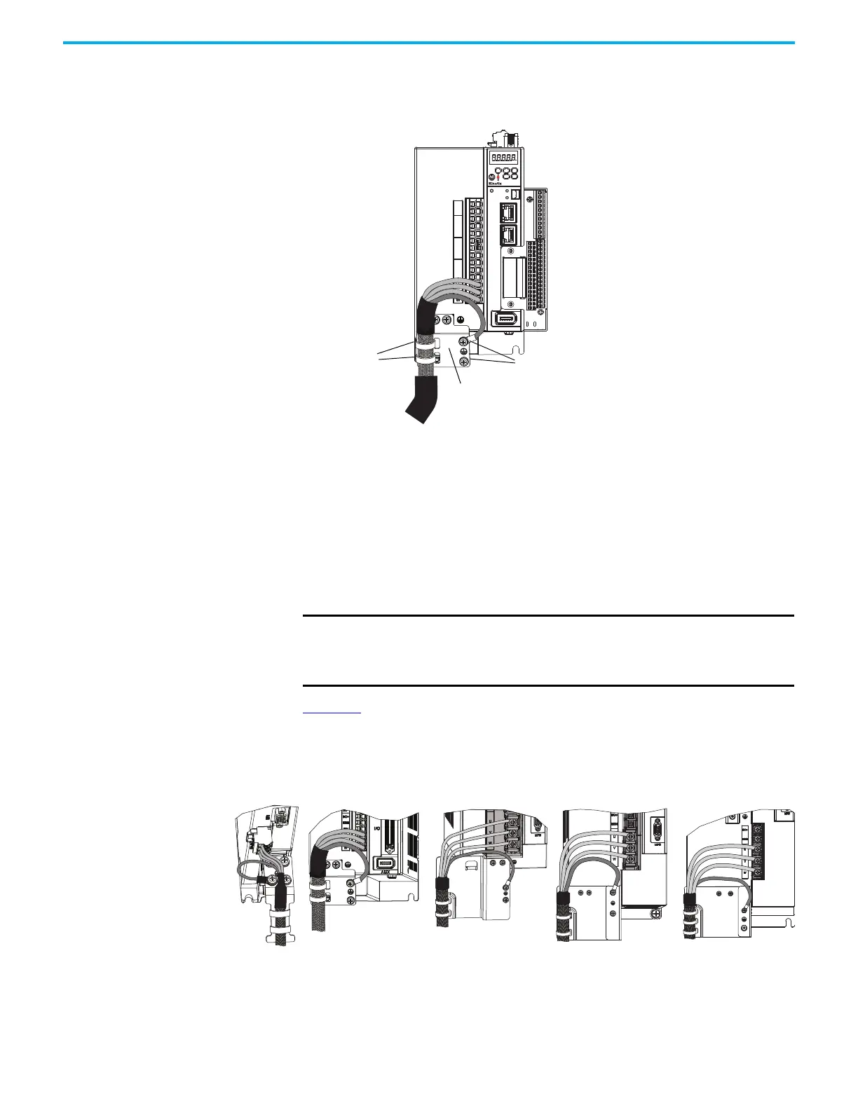
Follow these steps to apply the cable shield clamp.
1. Route the conductors with service loops to provide stress relief to the
motor power and brake conductors.
2. Apply tie wraps through the ground plate slots and around the exposed
cable shield.
Make sure the cable clamp tightens around the cable shield and provides
a good bond between the cable shield and the drive chassis.
3. Attach the motor-power ground wire to one of the PE ground screws.
Tighten the PE ground screw to a maximum torque value of 2.0 N•m
(17.7 lb•in).
Figure 64
displays examples of how the motor cable conductors and shield can
be routed and attached for each of the servo drives.
Figure 64 - Kinetix 5100 Drive Ground Plate Examples
D
5100
2
1
NET
MOD
CHARGE
I/0
AUX
U
V
W
DC+
ISH
ESH
P1
P2
DC–
L1
L2
L3
L1C
L2C
Tie Wraps
PE Ground Screws
Grounding Plate
IMPORTANT
If the power/brake cable shield has a loose fit between the ground
plate and tie wraps, the cable shield ground is ineffective. When the
tie wraps are pulled tight, the result must be a high-frequency bond
between the cable shield and the drive chassis.
2198-E1004-ERS
2198-E1007-ERS
2198-E1015-ERS
2198-E1020-ERS
2198-E2030-ERS
2198-E2055-ERS
2198-E4055-ERS
2198-E2075-ERS
2198-E4075-ERS
2198-E2150-ERS
2198-E4150-ERS
2198-E4004-ERS
2198-E4007-ERS
2198-E4015-ERS
2198-E4020-ERS
2198-E4030-ERS

 Loading...


