1-37
Cisco ONS 15454 DWDM Reference Manual, R8.5
78-18343-02
Chapter 1 Shelf Assembly Hardware
1.10 Ethernet Adapter Panel
1.10 Ethernet Adapter Panel
An ethernet adapter panel (EAP) is required in an ANSI or ETSI equipment rack for multishelf
configurations. Two EAPs are required in a multishelf configuration, one for each MS-ISC-100T card.
Figure 1-36 shows an example of two installed EAPs and the connection between each EAP and a node
controller shelf and a subtending shelf.
An EAP cable is used to connect the MS-ISC-100T card ports to the EAP (Figure 1-37). The nine
connector ends plug into Ports 0 through 8 of the MS-ISC-100T card, and the multiport connector plugs
into the EAP. Ports 0 and 1 on the MS-ISC-100T card are the DCN ports; Ports 2 through 7 are the SSC
ports. A cross-over (CAT-5) LAN cable is used to connect the DCN port on the EAP to the front panel
of the TCC2/TCC2P cards in the subtending shelves.
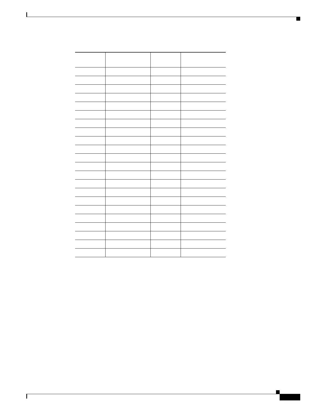
5 COM_3 31 —
6 NO_3 32 NO_4
7— 33COM_4
8 COM_5 34 —
9 NO_5 35 NO_6
10 — 36 COM_6
11 COM_7 37 —
12 NO_7 38 NO_8
13 — 39 COM_8
14 COM_9 40 —
15 NO_9 41 NO_10
16 — 42 COM_10
17 COM_11 43 —
18 NO_11 44 NO_12
19 — 45 COM_12
20 COM_13 46 —
21 NO_13 47 NO_14
22 — 48 COM_14
23 COM_15 49 —
24 NO_15 50 —
25 — 51 GND1
26 NO_0 52 GND2
Table 1-8 Pin Association for Alarm Output Pins (continued)
AMP Champ
Pin Number Signal Name
AMP Champ
Pin Number Signal Name

 Loading...


