1-54
Cisco ONS 15454 DWDM Reference Manual, R8.5
78-18343-02
Chapter 1 Shelf Assembly Hardware
1.14 Power and Ground Description
1.14 Power and Ground Description
Ground the equipment according to Telcordia standards or local practices. The following sections
describe power and ground for the ONS 15454 shelves.
1.14.1 ONS 15454 ANSI Power and Ground
Cisco recommends the following wiring conventions, but customer conventions prevail:
• Red wire for battery connections (–48 VDC).
• Black wire for battery return connections (0 VDC).
• The battery return connection is treated as DC-I, as defined in Telcordia GR-1089-CORE, Issue 3.
The ONS 15454 ANSI has redundant –48 VDC #8 power terminals on the shelf-assembly backplane.
The terminals are labeled BAT1, RET1, BAT2, and RET2 and are located on the lower section of the
backplane behind a clear plastic cover.
To install redundant power feeds, use four power cables and one ground cable. For a single power feed,
only two power cables (#10 AWG, copper conductor, 194 degrees F [90 degrees C]) and one ground
cable (#6 AWG) are required. Use a conductor with low impedance to ensure circuit overcurrent
protection. However, the conductor must have the capability to safely conduct any faulty current that
might be imposed.
The existing ground post is a #10-32 bolt. The nut provided for a field connection is also a #10 AWG,
with an integral lock washer. The lug must be a dual-hole type and rated to accept the #6 AWG cable.
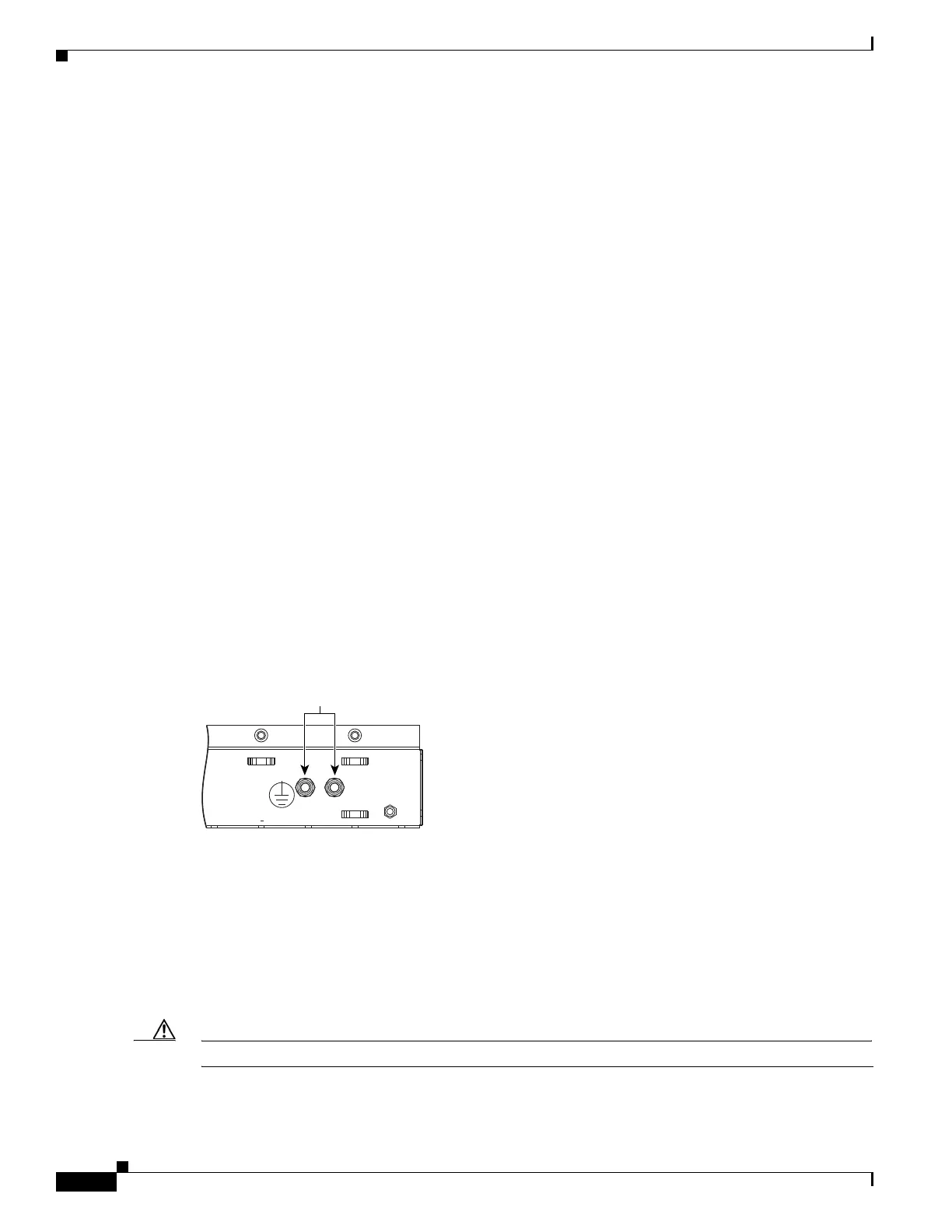
Two posts are provided on the ONS 15454 ANSI to accommodate the dual-hole lug. Figure 1-52 shows
the location of the ground posts.
Figure 1-52 Ground Posts on the ONS 15454 ANSI Backplane
1.14.2 ONS 15454 ETSI Power and Ground
The ONS 15454 ETSI has redundant –48 VDC power connectors on the MIC-A/P and MIC-C/T/P
faceplates. To install redundant power feeds, use the two power cables shipped with the
ONS 15454 ETSI and one ground cable. For details, see the “2.6.1 MIC-A/P FMEC” section on
page 2-18 and the “2.6.2 MIC-C/T/P FMEC” section on page 2-21.
Caution Only use the power cables shipped with the ONS 15454 ETSI.
FRAME GROUND
61852
Attach #6 AWG

 Loading...


