1-41
Cisco ONS 15454 DWDM Reference Manual, R8.5
78-18343-02
Chapter 1 Shelf Assembly Hardware
1.12.1 Fiber Management
Note You can remove the fiber guide, if necessary, to create a larger opening (if you need to route
CAT-5 Ethernet cables out the side, for example). To remove the fiber guide, take out the
three screws that anchor it to the side of the shelf assembly.
• Cable tie-wrap facilities on EIAs that secure cables to the cover panel (ANSI only)
• Reversible jumper routing fins that enable you to route cables out either side by positioning the fins
as desired
• Jumper slack storage reels (2) on each side panel that reduce the amount of slack in cables that are
connected to other devices
Note To remove the jumper slack storage reels, take out the screw in the center of each reel.
• Optional fiber-storage tray (recommended for DWDM nodes)
• Optional tie-down bar (ANSI only)
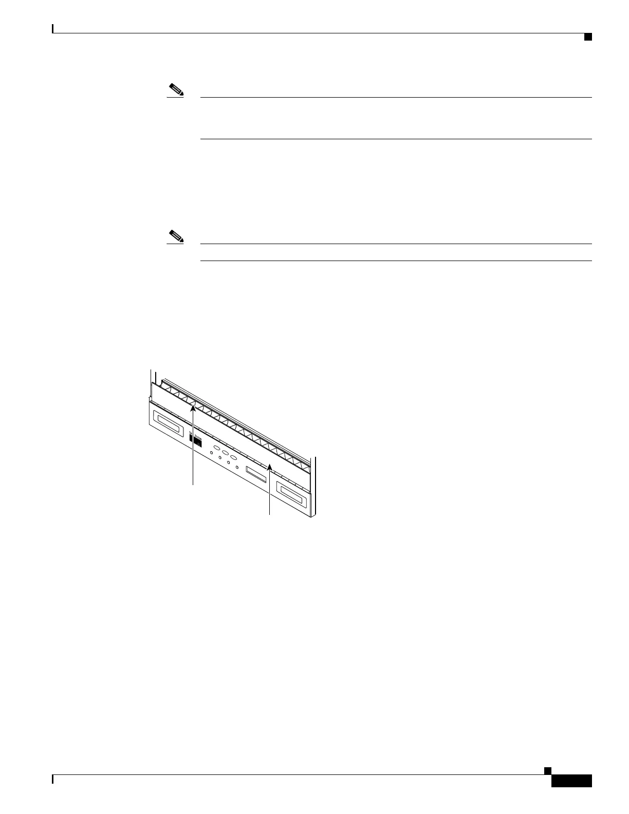
Figure 1-39 shows the cable management facilities that you can access through the fold-down front door,
including the cable-routing channel and the jumper routing fins.
Figure 1-39 Managing Cables on the Front Panel
1.12.1 Fiber Management
The jumper routing fins are designed to route fiber jumpers out of both sides of the shelf. Slots 1 to 6
exit to the left, and Slots 12 to 17 exit to the right. Figure 1-40 shows fibers routed from cards in the left
slots, down through the fins, then exiting out the fiber channel to the left. The maximum capacity of the
fiber routing channel depends on the size of the fiber jumpers.
F
A
N
F
A
IL
C
R
IT
M
A
J
M
IN
34238
Reversible jumper
routing fins
Fold down
front door

 Loading...


