12-17
Cisco ONS 15454 DWDM Reference Manual, R8.5
78-18343-02
Chapter 12 Cisco Transport Controller Operation
12.5.3 Network View
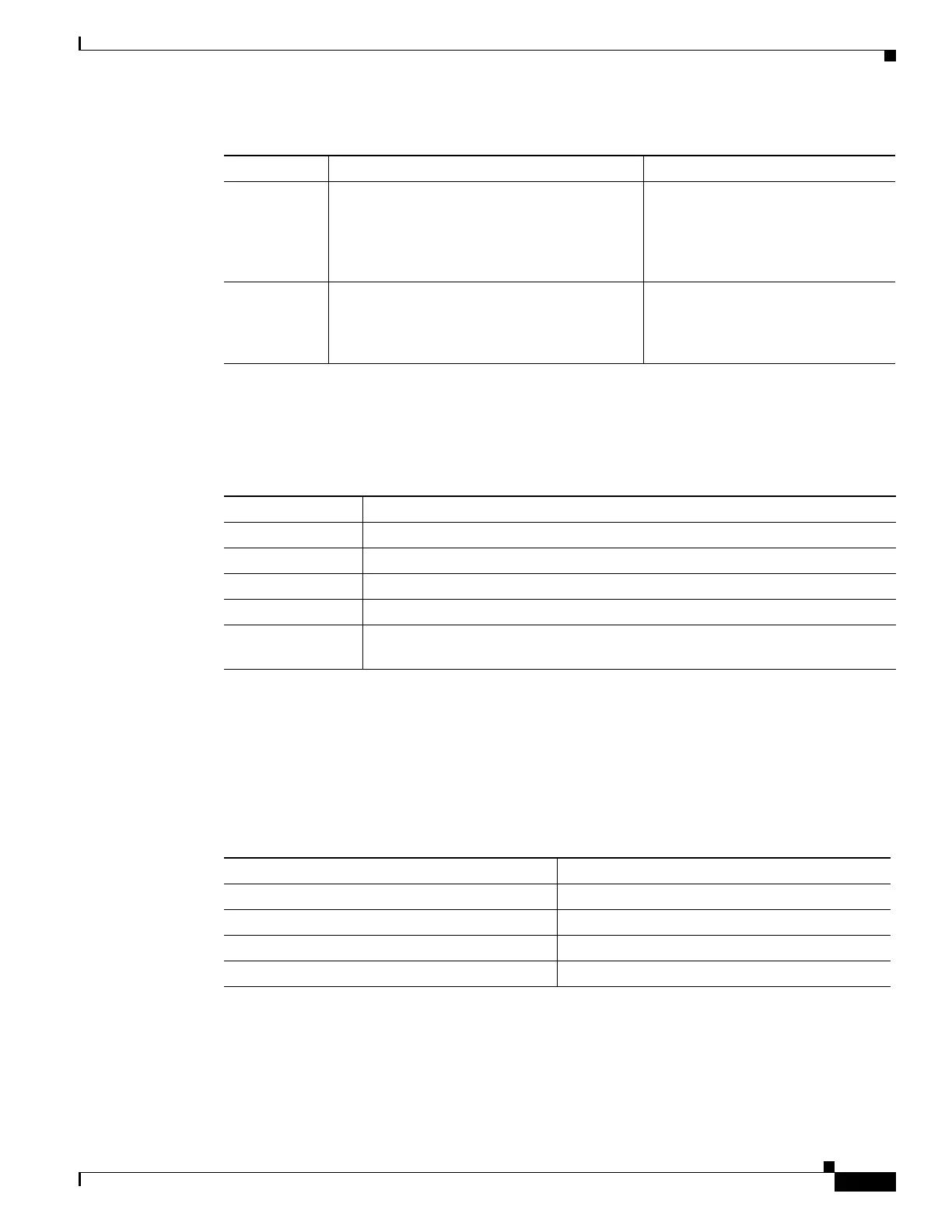
12.5.3.2 CTC Node Colors
The color of a node in network view, shown in Table 12-11, indicates the node alarm status.
12.5.3.3 DCC Links
The lines show DCC connections between the nodes (Table 12-12). DCC connections can be green
(active) or gray (fail). The lines can also be solid (circuits can be routed through this link) or dashed
(circuits cannot be routed through this link). Circuit provisioning uses active/routable links. Selecting a
node or span in the graphic area displays information about the node and span in the status area.
12.5.3.4 Link Consolidation
CTC provides the ability to consolidate the DCC, generic communications channel (GCC), optical
transmission section (OTS), and PPC links shown in the network view into a more streamlined view.
Link consolidation allows you to condense multiple inter-nodal links into a single link. The link
Provisioning Provisions security, alarm profiles,
bidirectional line switched rings (BLSRs)
(ANSI), multiplex section-shared protection
rings (MS-SPRing) (ETSI), and overhead
circuits.
Security, Alarm Profiles, BLSR
(ANSI), MS-SPRing (ETSI),
Overhead Circuits, Provisionable
Patchcords
Maintenance Displays the type of equipment and the status
of each node in the network; displays working
and protect software versions; and allows
software to be downloaded.
Software
Table 12-10 Network View Tabs and Subtabs (continued)
Tab Description Subtabs
Table 12-11 Node Status Shown in Network View
Color Alarm Status
Green No alarms
Yellow Minor alarms
Orange Major alarms
Red Critical alarms
Gray with
Unknown#
Node initializing for the first time (CTC displays Unknown# because CTC has
not discovered the name of the node yet)
Table 12-12 DCC Colors Indicating State in Network View
Color and Line Style State
Green and solid Active/Routable
Green and dashed Active/Nonroutable
Gray and solid Failed/Routable
Gray and dashed Failed/Nonroutable

 Loading...


