3-7
Cisco ONS 15454 DWDM Reference Manual, R8.5
78-18343-02
Chapter 3 Optical Service Channel Cards
3.3.1 Power Monitoring
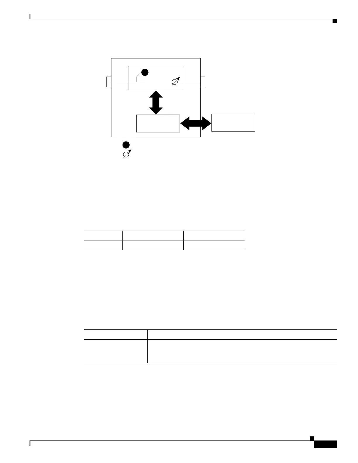
Figure 3-7 OSCM VOA Optical Module Functional Block Diagram
3.3.1 Power Monitoring
Physical photodiode P1 monitors the power for the OSCM card. The returned power level value is
calibrated to the OSC TX port (Table 3-3).
For information on the associated TL1 AIDs for the optical power monitoring points, refer the “CTC
Port Numbers and TL1 Aids” section in Cisco ONS SONET TL1 Command Guide, Release 8.5.
3.3.2 OSCM Card-Level Indicators
The OSCM card has three card-level LED indicators, described in Table 3-4.
P1
P1
OSC TX
Physical photodiode
OSC Variable optical attenuator
Control
Module
OSC RX
Control
Interface
124968
Table 3-3 OSCM VOA Port Calibration
Photodiode CTC Type Name Calibrated to Port
P1 Output OSC OSC TX
Table 3-4 OSCM Card-Level Indicators
Card-Level Indicators Description
Red FAIL LED The red FAIL LED indicates that the card’s processor is not ready or that
there is an internal hardware failure. Replace the card if the red FAIL LED
persists.

 Loading...


