5-20
Cisco ONS 15454 DWDM Reference Manual, R8.5
78-18343-02
Chapter 5 Multiplexer and Demultiplexer Cards
5.4.2 32DMX-O Card-Level Indicators
For information on the associated TL1 AIDs for the optical power monitoring points, refer the “CTC
Port Numbers and TL1 Aids” section in Cisco ONS SONET TL1 Command Guide, Release 8.5.
5.4.2 32DMX-O Card-Level Indicators
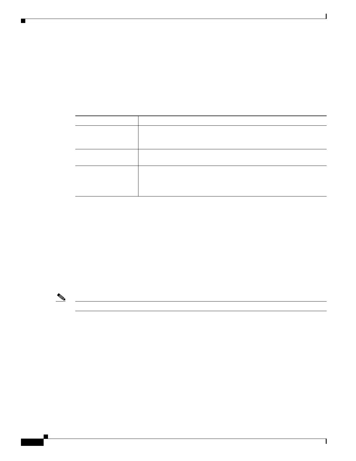
The 32DMX-O card has three card-level LED indicators, described in Table 5-12.
5.4.3 32DMX-O Port-Level Indicators
You can find the status of the card ports using the LCD screen on the ONS 15454 fan-tray assembly. Use
the LCD to view the status of any port or card slot; the screen displays the number and severity of alarms
for a given port or slot. The 32DMX-O card has five sets of ports located on the faceplate. MON is the
output monitor port. COM RX is the line input. The xx.x to yy.y TX ports represent the four groups of
eight channels ranging from wavelength xx.x to wavelength yy.y according to the channel plan.
5.5 4MD-xx.x Card
Note See the “A.6.3 4MD-xx.x Card Specifications” section on page A-20 for hardware specifications.
The 4-Channel Multiplexer/Demultiplexer (4MD-xx.x) card multiplexes and demultiplexes four
100-GHz-spaced channels identified in the channel plan. The 4MD-xx.x card is designed to be used with
band OADMs (both AD-1B-xx.x and AD-4B-xx.x).
The card is bidirectional. The demultiplexer and multiplexer functions are implemented in two different
sections of the same card. In this way, the same card can manage signals flowing in opposite directions.
There are eight versions of this card that correspond with the eight sub-bands specified in Table 5-13 on
page 5-23. The 4MD-xx.x can be installed in Slots 1 to 6 and 12 to 17.
The 4MD-xx.x has the following features implemented inside a plug-in optical module:
• Passive cascade of interferential filters perform the channel multiplex/demultiplex function.
• Software-controlled VOAs at every port of the multiplex section regulate the optical power of each
multiplexed channel.
Table 5-12 32DMX-O Card-Level Indicators
Card-Level Indicators Description
Red FAIL LED The red FAIL LED indicates that the card’s processor is not ready or that
there is an internal hardware failure. Replace the card if the red FAIL LED
persists.
Green ACT LED The green ACT LED indicates that the 32DMX-O is carrying traffic or is
traffic-ready.
Amber SF LED The amber SF LED indicates a signal failure on one or more of the card’s
ports. The amber SF LED also illuminates when the transmit and receive
fibers are incorrectly connected. When the fibers are properly connected, the
light turns off.

 Loading...


