10-23
Cisco ONS 15454 DWDM Reference Manual, R8.5
78-18343-02
Chapter 10 Network Reference
10.7.3 Fiber Cut Scenarios
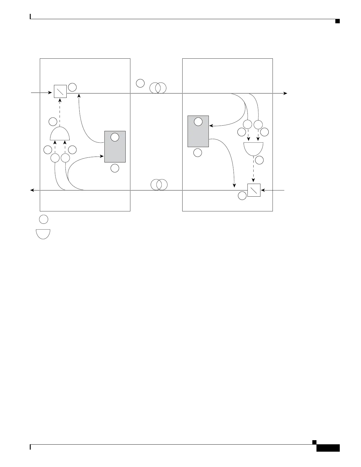
Figure 10-15 Nodes Using OSC-CSM Cards
Two photodiodes at the Node B OSC-CSM card monitor the received signal strength for the received
optical payload and OSC signals. When the fiber is cut, LOS is detected at both of the photodiodes. The
AND function then indicates an overall LOS condition, which causes the Node B OSC laser to shut down
and the optical switch to block traffic. This in turn leads to LOS for both the optical payload and OSC
signals at Node A, which causes Node A to turn off the OSC laser and the optical switch to block
outgoing traffic. The sequence of events after a fiber cut is as follows (refer to the numbered circles in
Figure 10-15):
1. Fiber is cut.
2. The Node B power monitoring photodiode detects a LOS-P on the OSC-CSM card. Refer to the
Cisco ONS 15454 DWDM Troubleshooting Guide.
3. On the OSC-CSM, the simultaneous LOS-O and LOS-P detection triggers a change in the position
of the optical switch. CTC reports a LOS alarm (loss of continuity), while LOS-O and LOS-P are
demoted. Refer to the Cisco ONS 15454 DWDM Troubleshooting Guide.
4. The optical switch blocks outgoing traffic.
5. The OSC laser is shut down.
6. The Node A power monitoring photodiode detects a LOS-O on the OSC-CSM card. Refer to the
Cisco ONS 15454 DWDM Troubleshooting Guide.
7. The Node A power monitoring photodiode detects a LOS-P on the OSC-CSM card. Refer to the
Cisco ONS 15454 DWDM Troubleshooting Guide.
OSC-CSM
P
P
P
OSC
OSC-CSM
PP
OSC
= power monitoring photodiode
= logical AND function
Node A
Side B
Node B
Side A
X
11
1
9
8 7
10
6
2 3
4
5
2
7
120987

 Loading...


