5-16
Cisco ONS 15454 DWDM Reference Manual, R8.5
78-18343-02
Chapter 5 Multiplexer and Demultiplexer Cards
5.3.2 Power Monitoring
5.3.2 Power Monitoring
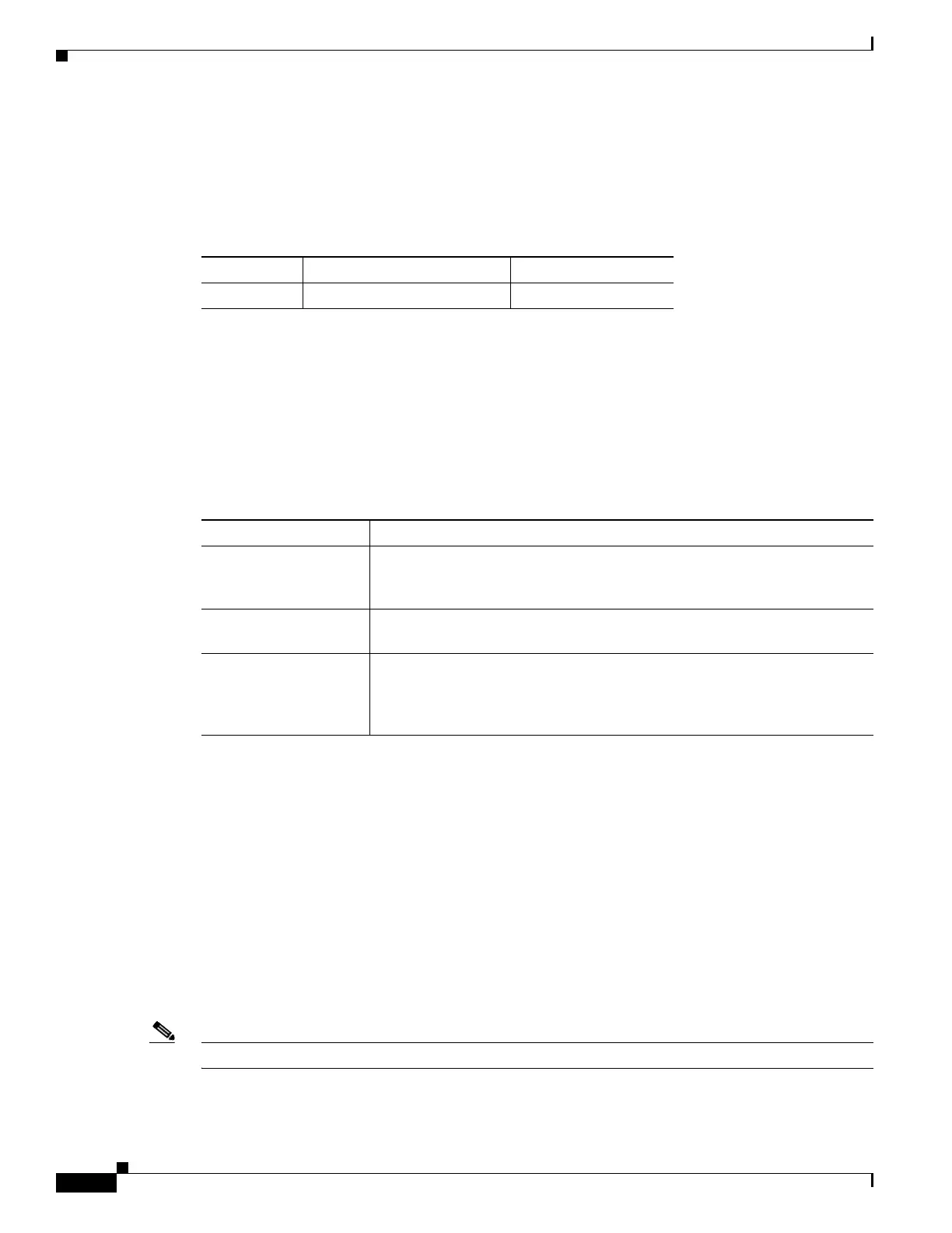
Physical photodiodes P1 through P32 monitor the power for the 32MUX-O card. The returned power
level values are calibrated to the ports as shown in Table 5-9.
For information on the associated TL1 AIDs for the optical power monitoring points, refer the “CTC
Port Numbers and TL1 Aids” section in Cisco ONS SONET TL1 Command Guide, Release 8.5.
5.3.3 32MUX-O Card-Level Indicators
The 32MUX-O card has three card-level LED indicators, described in Table 5-10.
5.3.4 32MUX-O Port-Level Indicators
You can find the status of the card ports using the LCD screen on the ONS 15454 fan-tray assembly. Use
the LCD to view the status of any port or card slot; the screen displays the number and severity of alarms
for a given port or slot. The 32MUX-O card has five sets of ports located on the faceplate.
COM TX is the line output. COM MON is the optical monitoring port. The xx.x to yy.y RX ports
represent the four groups of eight channels ranging from wavelength xx.x to wavelength yy.y, according
to the channel plan.
5.4 32DMX-O Card
Note See the “A.6.2 32DMX-O Card Specifications” section on page A-19 for hardware specifications.
Table 5-9 32MUX-O Port Calibration
Photodiode CTC Type Name Calibrated to Port
P1–P32 ADD COM TX
Table 5-10 32MUX-O Card-Level Indicators
Card-Level Indicators Description
Red FAIL LED The red FAIL LED indicates that the card’s processor is not ready or that
there is an internal hardware failure. Replace the card if the red FAIL LED
persists.
Green ACT LED The green ACT LED indicates that the 32MUX-O is carrying traffic or is
traffic-ready.
Amber SF LED The amber SF LED indicates a signal failure on one or more of the card’s
ports. The amber SF LED also illuminates when the transmit and receive
fibers are incorrectly connected. When the fibers are properly connected, the
light turns off.

 Loading...


